Screw for juice extractor
A juicer and screw technology, applied in the field of juicers, can solve the problems of easy blockage, burnout of the motor, and stoppage of the screw.
- Summary
- Abstract
- Description
- Claims
- Application Information
AI Technical Summary
Problems solved by technology
Method used
Image
Examples
Embodiment 1
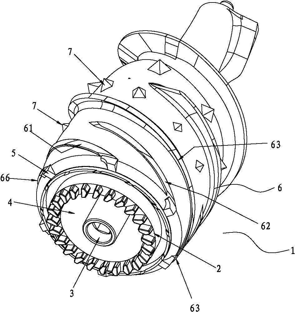
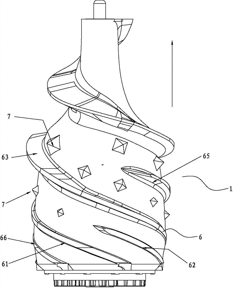
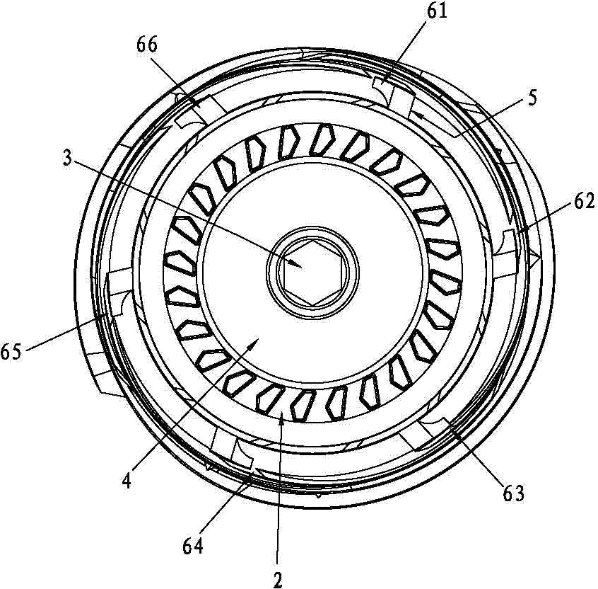
[0024] Such as figure 1 , figure 2 , image 3 As shown, a screw for a juice extractor includes a screw body 1, the screw body 1 includes a screw thread 6 on the surface of the screw body, an inner ring 2 protruding downward from the lower end of the screw body 1, and an inner ring 2 located at the inner ring 2. The rotating shaft 3 on the lower end surface of the inner screw body 1, the lower opening space 4 between the inner ring and the rotating shaft, and the discharge claw 5 on the lower end surface of the screw body radially outside the inner ring 2 at the beginning of the thread line; Protrusions 7 are arranged between the threaded lines.
[0025] The protrusion 7 is conical or truncated;
[0026] It can also be: the protrusion 7 is in the shape of a cone, a triangular pyramid, a quadrangular pyramid, a pentagonal pyramid or a hexagonal pyramid;
[0027] There are several threads 6 on the screw body 1 .
Embodiment 2
[0029] Such as figure 1 , figure 2 , image 3 As shown, a screw for a juice extractor includes a screw body 1, the screw body 1 includes a screw thread 6 on the surface of the screw body, an inner ring 2 protruding downward from the lower end of the screw body 1, and an inner ring 2 located at the inner ring 2. The rotating shaft 3 on the lower end surface of the inner screw body 1, the lower opening space 4 between the inner ring and the rotating shaft, and the discharge claw 5 on the lower end surface of the screw body radially outside the inner ring 2 at the beginning of the thread line; including several protrusions 7,
[0030] The protrusion 7 is in the shape of a cone, a triangular pyramid, a quadrangular pyramid, a pentagonal pyramid or a hexagonal pyramid;
[0031] Such as figure 1 , figure 2 , image 3 , Figure 4 , Figure 5 , Figure 6 As shown, there are six threads 6 on the screw body 1, which are divided into a first thread 61, a second thread 62, a th...
Embodiment 3
[0035] refer to figure 1 , figure 2 , image 3 , Figure 4 , Figure 5 , Figure 6 shown.
[0036] There are three threads on the screw body 1, which are divided into a first thread, a second thread and a third thread;
[0037] The second thread line is a solid thread line from the second thread line at the bottom of the screw body to 90 degrees of rotation, and the thread line from the second thread line at the bottom of the screw body to 90 degrees is composed of several protrusions.
PUM
 Abstract
Description
Claims
Application Information
 - R&D
- Intellectual Property
- Life Sciences
- Materials
- Tech Scout
- Unparalleled Data Quality
- Higher Quality Content
- 60% Fewer Hallucinations
Browse by: Latest US Patents, China's latest patents, Technical Efficacy Thesaurus, Application Domain, Technology Topic, Popular Technical Reports.
© 2025 PatSnap. All rights reserved.Legal|Privacy policy|Modern Slavery Act Transparency Statement|Sitemap|About US| Contact US: help@patsnap.com


