Time-delay boosting electric pressure cooker

A technology of boosting voltage and pressure cooker, which is applied to pressure cooker, cooking utensils, household utensils, etc. It can solve the problems of increasing cleaning time, not being able to clean the pot cover, and not being able to control the pressure with an electric pressure cooker, so as to improve convenience and save energy. Cleaning time, to avoid the effect that cannot be cleaned

Inactive Publication Date: 2018-11-20
黄文才
View PDF0 Cites 59 Cited by
  • Summary
  • Abstract
  • Description
  • Claims
  • Application Information

AI Technical Summary

Problems solved by technology

[0003] At present, the existing electric pressure cooker still has some deficiencies, for example; the existing electric pressure cooker cannot control the pressure inside the pot when the electric pressure cooker is cooking rice, and when the pot is in a semi-high pressure state, it can quickly absorb moisture and cannot After the set time is reached, the solenoid valve is controlled by the controller to close, and then the pressure in the pot continues to increase. In addition, the existing electric pressure cooker generally fixes the pot cover on the pot body, which may easily cause corners in the pot cover during cleaning. The phenomenon that the electric pressure cooker cannot be cleaned at all places reduces the convenience of cleaning the electric pressure cooker and increases the cleaning time. When the pot liner is extracted from the pot body, it is easy to cause burns when the pot liner is extracted, which reduces the extraction of the pot liner. Convenience and flexibility when using the pot

Method used


Image

  • Time-delay boosting electric pressure cooker
  • Time-delay boosting electric pressure cooker
  • Time-delay boosting electric pressure cooker

Examples


Embodiment Construction

[0023] In order to make the technical means, creative features, goals and effects achieved by the present invention easy to understand, the present invention will be further described below in conjunction with specific embodiments.

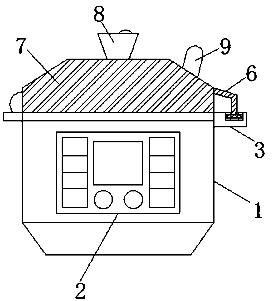
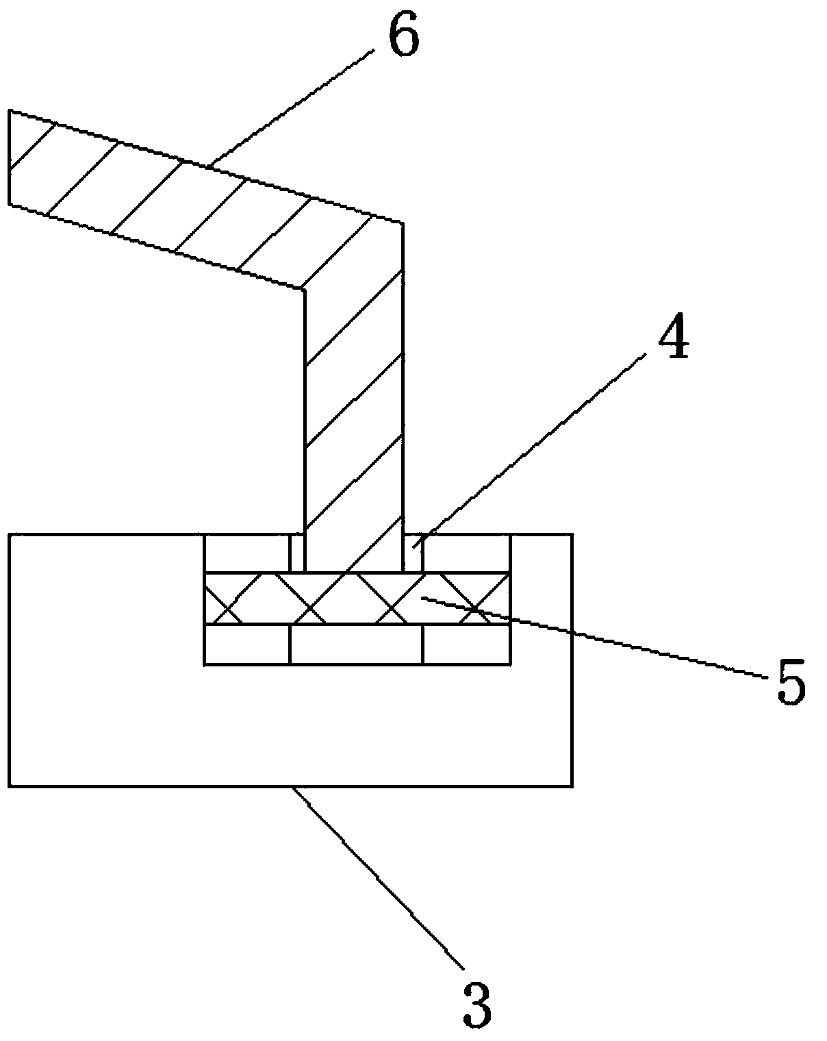
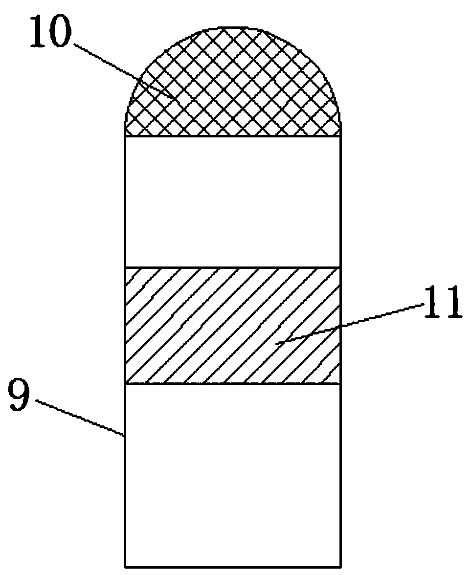
[0024] see Figure 1-5 , the present invention provides a technical solution: a time-delayed step-up electric pressure cooker, including a pot body 1, on which a controller 2, a connecting plate 3, a chute 4, a slider 5, and a support rod 6 are arranged. , a pot cover 7, a handle 8, an exhaust column 9, an air outlet head 10 and a solenoid valve 11, the controller 2 is fixedly connected to the front of the pot body 1, and the connecting plate 3 is fixedly connected to the pot The upper right of the body 1, the chute 4 is located inside the connecting plate 3, the slider 5 is movably connected inside the chute 4, and the support rod 6 is fixedly connected to the inside of the slider 5 The upper end, the pot cover 7 is fixedly connected to the left...


PUM


Abstract

The invention discloses a time-delay boosting electric pressure cooker which comprises a cooker body, wherein a controller, a connecting plate, a sliding chute, a sliding block, a supporting rod, a cooker cover, a handle, an exhausting column, a gas outlet head and an electromagnetic valve are arranged on the cooker body; the controller is fixedly connected in front of the cooker body; the connecting plate is fixedly connected to the upper right of the cooker body; the sliding chute is located inside the connecting plate; the sliding block is movably connected inside the sliding chute; the supporting rod is fixedly connected to an upper end of the sliding block; the cooker cover is fixedly connected to a left end of the supporting rod; and the handle is fixedly connected to an upper end ofthe cooker cover. The controller, the electromagnetic valve and a temperature sensor can be combined to effectively control the pressure in the electric pressure cooker when cooking rice, and rapidlyabsorb enough water when the interior of the cooker is in a semi-high pressure state; the electromagnetic valve is controlled to be closed by the controller after reaching a set time, and then the cooker continues to boost.

Description

technical field [0001] The invention relates to the technical field of household appliances, in particular to a time-delay boost electric pressure cooker. Background technique [0002] Electric pressure cooker is an upgraded product of traditional pressure cooker and electric rice cooker. It combines the advantages of pressure cooker and electric rice cooker, completely solves the safety problem of pressure cooker, and removes the safety hazard that ordinary pressure cooker has plagued consumers for many years. [0003] At present, the existing electric pressure cooker still has some deficiencies, for example; the existing electric pressure cooker cannot control the pressure inside the pot when the electric pressure cooker is cooking rice, and when the pot is in a semi-high pressure state, it can quickly absorb moisture and cannot After the set time is reached, the solenoid valve is controlled by the controller to close, and then the pressure in the pot continues to increase...

Claims


Application Information

Patent Timeline
Patent Type & Authority Applications(China)
IPC IPC(8): A47J27/08A47J27/086A47J27/092
CPCA47J27/08A47J27/0802A47J27/086A47J27/092
Inventor 黄文才王世文
Owner 黄文才
Why Eureka
Try Eureka