
Compression atomizer
A nebulizer and compression type technology, applied in the direction of nebulizer for treatment, can solve the problems of adverse environmental impact, unfavorable patient treatment, large vibration, etc., to reduce noise, improve the suction power, and prolong the use time.
- Summary
- Abstract
- Description
- Claims
- Application Information
AI Technical Summary
Problems solved by technology
Method used
Image

Examples
Embodiment Construction
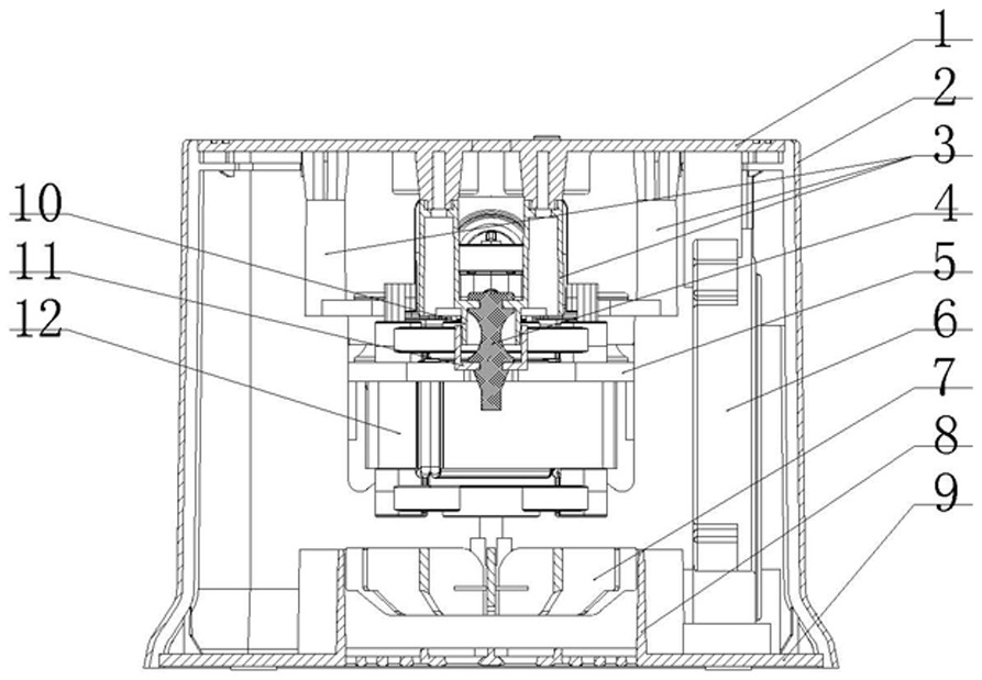
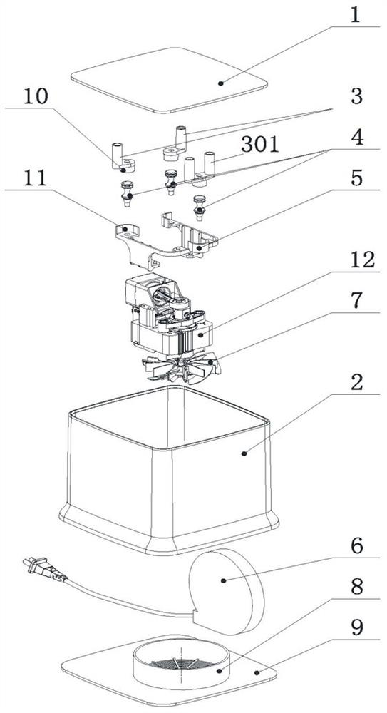
[0015] refer to figure 1 , figure 2 Shown: a compression type atomizer is designed, which is provided with a main engine bottom shell 9, a compression main engine 12 and a coaxial fan 7, a middle shell 2 is connected to the main engine bottom shell 9, and an upper cover 1 is arranged on the top of the middle shell 2 , There is a suspension device on the inner surface of the upper cover 1, the compressor main engine 12 is connected with the suspension device, and a fan duct 8 is arranged at the bottom of the main engine bottom shell 9, and the coaxial fan 7 is placed in the fan duct 8.
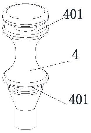
[0016] refer to image 3 , Figure 4 , Figure 5 , Image 6 The suspension device includes three elastic buffer bodies 4 with columnar structures. The outer circumference of the elastic buffer main body 4 is provided with upper and lower parallel annular grooves 401 at intervals, and there are also two annular grooves 401 connected to the inner side of the upper cover 1. The single-column...
PUM
 Abstract
Description
Claims
Application Information