A fixture structure for plunger chute machining

A specific structure and fixture technology, which is applied in the direction of manufacturing tools, metal processing, metal processing equipment, etc., can solve the problems of measuring chute scrapping of gauges, high design and manufacturing costs, and out-of-tolerance gauge dimensions, so as to achieve adjustability and processing The effect of short time and reduced clamping frequency

Active Publication Date: 2016-04-13
WUXI CITY PEIJI MACHINERY
View PDF6 Cites 0 Cited by
  • Summary
  • Abstract
  • Description
  • Claims
  • Application Information

AI Technical Summary

Problems solved by technology

[0004] (2) The pre-tightening force provided by the operator when placing the plunger needs to be consistent, too loose or too tight will cause the gauge to be scrapped when measuring the chute
[0005] (3) The plunger is easy to move during the clamping process, causing the gauge size to be out of tolerance
[0006] (4) Since the plunger structure needs to be processed with two inclined grooves, it needs to be clamped twice, resulting in high frequency of clamping, greatly wasting processing time, time-consuming and labor-intensive, and reducing processing accuracy
[0007] (5) Due to the variety of plungers, the angle between the processing chute and the flat position of the plunger (the flat position is a flat surface on the plunger) is different, so a set of fixtures is only suitable for one type , For different types of plungers, different fixtures need to be processed, the design and manufacturing costs are high, and the inventory is increased

Method used


Image

  • A fixture structure for plunger chute machining

Examples


Embodiment Construction

[0025] The specific implementation manner of the present invention will be described below in conjunction with the accompanying drawings.

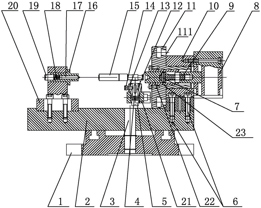
[0026] like figure 1 As shown, a fixture structure for plunger chute processing includes a chassis 1, and the chassis (1) is positioned and connected with the positioning round pin 3 of the bottom plate 2, and the first top mechanism and the clamp mechanism are respectively fixed on the bottom plate 2. The two top mechanisms are installed inside the clamp mechanism, and a positioning mechanism is also installed on the clamp mechanism;

[0027] The specific structure of the clamp mechanism is as follows: it includes a clamp body 10 affixed to the base plate 2 through a fastener 6, one end of the clamp body 10 is connected to the cylinder 8, and the other end of the clamp body 10 is connected to the boss end surface 111 of the dial 11 abutting against each other, one end of the dial 11 extends outward and extends into the clamp body 10;

...


PUM


Abstract

The invention relates to a clamping structure for machining plunger inclined grooves. The clamping structure comprises base disc which in location connection with a location round pin of a bottom plate. A first center mechanism and a clamp mechanism are fixedly connected onto the bottom plate respectively. A second center mechanism is arranged in the clamp mechanism, and a location mechanism is arranged on the clamp mechanism. According to the clamping structure, a center hole of one end and a cap of the other end of the plunger are clamped through a yin center and a yang center respectively, so that the circle center location of the two ends of the plunger is achieved, and the location reference is consistent with the design reference; the location mechanism is use, a location block of the location mechanism used for being attached to the plunger flat surface, the relative position of the plunger axis direction is adjustable through the yin center and the yang center, and the adjustability of the rotation direction and the machining angle is achieved through a dial.

Description

technical field [0001] The invention relates to a fixture structure, in particular to a fixture structure for machining inclined grooves of plungers. Background technique [0002] At present, the plunger chute processing fixture uses the "V" block to cooperate with the end face of the plunger for positioning, and the plunger is pressed together by the pressure plate and the screw. The clamping method of this fixture has the following disadvantages: [0003] (1) The processing of the plunger is positioned in the outer circle, which requires high consistency in the size of the plunger's outer circle. [0004] (2) The pre-tightening force provided by the operator when placing the plunger needs to be consistent, too loose or too tight will cause the gauge to be scrapped when measuring the chute. [0005] (3) The plunger is easy to move during the clamping process, causing the gauge size to be out of tolerance. [0006] (4) Since the plunger structure needs to be processed with...

Claims


Application Information

Patent Timeline
Patent Type & Authority Patents(China)
IPC IPC(8): B23Q3/08B23Q15/26
CPCB23Q1/26B23Q3/062B23Q3/082
Inventor 马军沈环
Owner WUXI CITY PEIJI MACHINERY
Why Eureka
Try Eureka