Clamp structure for machining spiral groove

A technology of helical groove and specific structure, applied in the direction of manufacturing tools, workpiece clamping devices, etc., can solve the problems of large occupied space, large design and manufacturing costs, etc., and achieve the effect of easy management, reduction of design costs, and realization of adjustability.

Active Publication Date: 2014-12-10
WUXI CITY PEIJI MACHINERY
View PDF5 Cites 0 Cited by
  • Summary
  • Abstract
  • Description
  • Claims
  • Application Information

AI Technical Summary

Problems solved by technology

[0008] (5) The fixture structure is only limited to the plunger processing of the spiral groove. Since the types of oil control grooves of the plunger parts are varied, it is necessary to design a variety of fixtures, which results in high design and manufacturing costs and large space occupation.

Method used


Image

  • Clamp structure for machining spiral groove
  • Clamp structure for machining spiral groove
  • Clamp structure for machining spiral groove

Examples


Embodiment Construction

[0031] The specific implementation manner of the present invention will be described below in conjunction with the accompanying drawings.

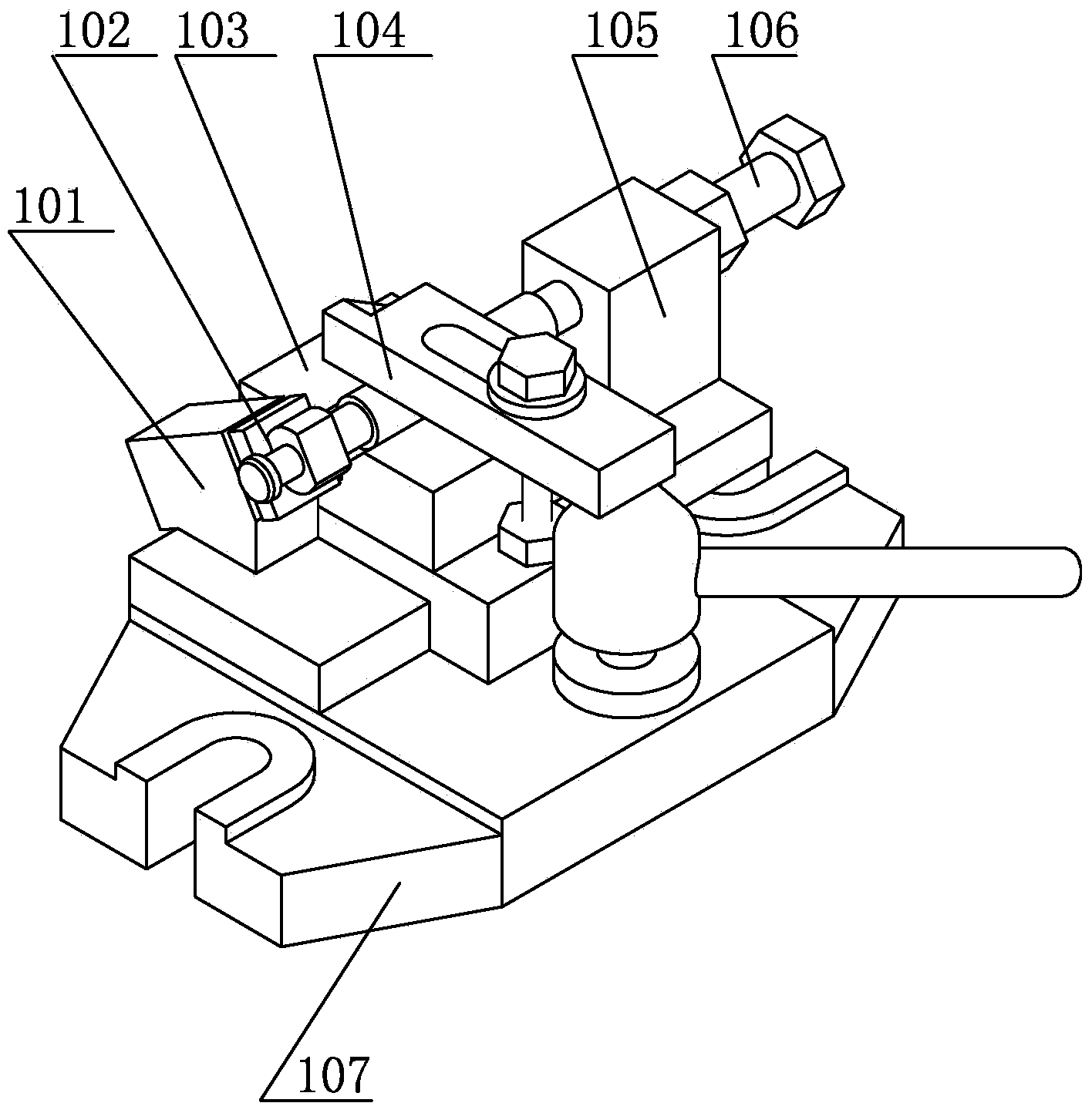
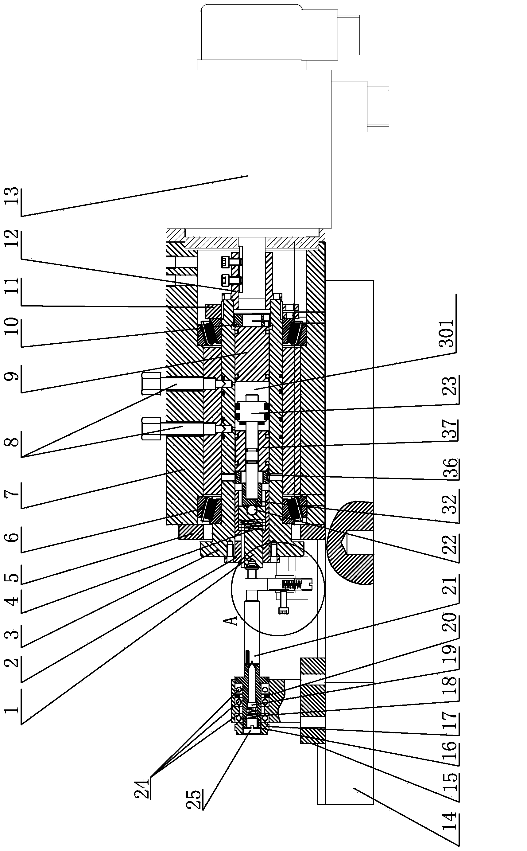
[0032] Such as figure 1 As shown, a fixture structure for processing spiral grooves includes a base plate 14 on which the first tip mechanism and the clamp mechanism are respectively slidably connected, and the second tip mechanism is installed in the clamp mechanism;

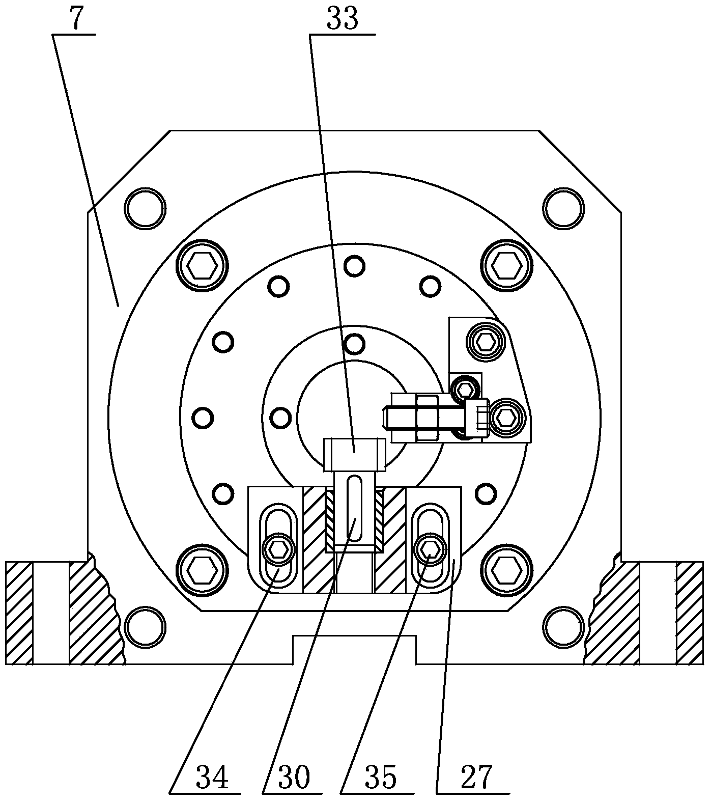
[0033] Such as figure 1 As shown, the specific structure of the clamp mechanism is as follows: comprising the clamp body 7, the output end of the motor 13 extends into the clamp body 7, and is connected with one end of the main shaft 3 located in the clamp body 7 through the connecting sleeve 12, and the connecting sleeve 12 extends into the clamp body 7. The part inside the clamp body 7 is locked by the first locking nut 10 . In the chuck body 7, the first bearing 6 is installed symmetrically on the outer circumference of the main shaft 3, and the first bearing 6 is a ta...


PUM


Abstract

The invention relates to a clamp structure for machining a spiral groove. The clamp structure is characterized by comprising a bottom plate, a first tip mechanism and a clamp mechanism are respectively in sliding connection with the bottom plate, and a second tip mechanism is arranged in the clamp mechanism; a central hole in one end of a plunger and a cover cap at the other end of the plunger are clamped by a female tip and a male tip respectively, circle centers of the two ends of the plunger can be located, and a locating basis is made to be consistent with an involved basis. An adjustable positioning mechanism is adopted, a positioning block is attached to the flat face of the plunger, meanwhile, the adjustable positioning mechanism is arranged on a main shaft and does 360-degree barrier-free rotation, the positioning block exerts force on the flat face of the plunger in the process of rotating along with the main shaft, the plunger is driven to rotate between the female tip and the male tip through the force action, the relative rotation of the plunger can be adjusted in the axial direction through the female tip and the male tip, and therefore adjustability of the rotation direction and the machining angle can be achieved.

Description

technical field [0001] The invention relates to a fixture structure, in particular to a fixture structure for processing spiral grooves. Background technique [0002] As an important part of the engine, the plunger is used to perform piston-like reciprocating motion when the engine is doing work. It has the characteristics of easy wear, so its demand is relatively large. At present, the existing processing fixtures for processing the spiral groove of the plunger are as follows: figure 1 As shown, it includes a bottom plate 107, on which a pressing plate 104 and a mounting block 105 are installed, the adjusting screw 105 passes through the mounting block 105, and a "V" shaped block for embedding the plunger is also installed on the bottom plate 107 103, on the front portion of the "V" shaped block 103, a positioning block 101 is also installed on the bottom plate 107. [0003] The processing process of the fixture is first to install the plunger in the "V" shaped b...

Claims


Application Information

Patent Timeline
IPC IPC(8): B25B11/00
CPCB25B11/00
Inventor 马军沈环
Owner WUXI CITY PEIJI MACHINERY
Why Eureka
Try Eureka