Landing gear

A landing gear and bracket frame technology, applied in landing gear, aircraft parts, chassis and other directions, can solve the problem that the landing gear is easy to block the camera's line of sight, and achieve the effect of smooth shooting and cost reduction.

Inactive Publication Date: 2014-04-30
张家港锐泰智能科技有限公司
View PDF6 Cites 7 Cited by
  • Summary
  • Abstract
  • Description
  • Claims
  • Application Information

AI Technical Summary

Problems solved by technology

[0004] The purpose of the present invention is to provide a retractable landing gear for an unmanned aerial v

Method used


Image

  • Landing gear
  • Landing gear
  • Landing gear

Examples


Embodiment Construction

[0030] The technical solutions in the embodiments of the present invention will be described in detail below in conjunction with the accompanying drawings in the embodiments of the present invention. Obviously, the described embodiments are only some of the embodiments of the present invention, not all of them. Based on the embodiments of the present invention, all other embodiments obtained by persons of ordinary skill in the art without making creative efforts belong to the protection scope of the present invention.

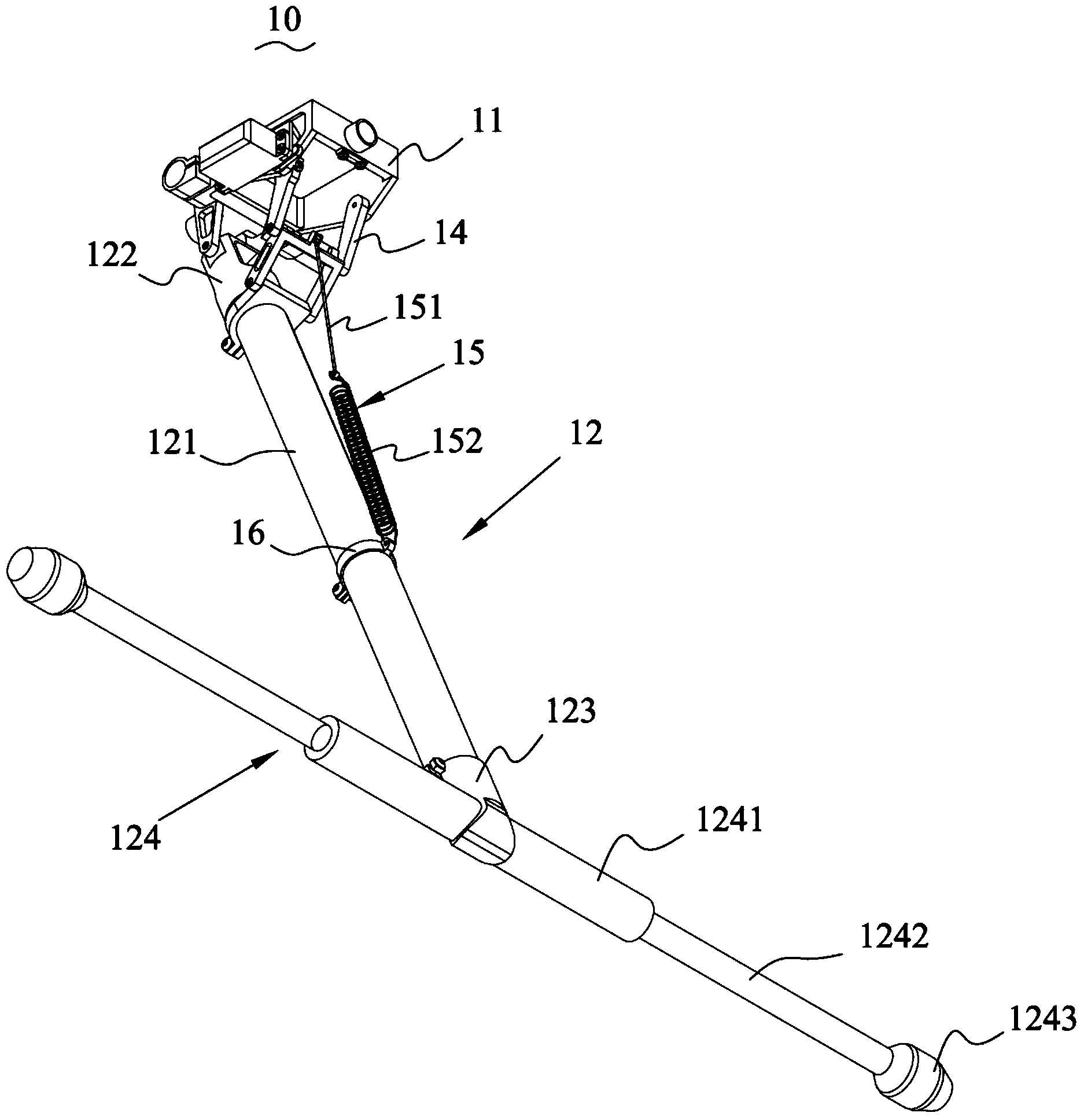
[0031] ginseng figure 1 As shown, the retractable landing gear 10 includes a support frame 11 and a support leg 12 rotatably connected to the support frame 11 .

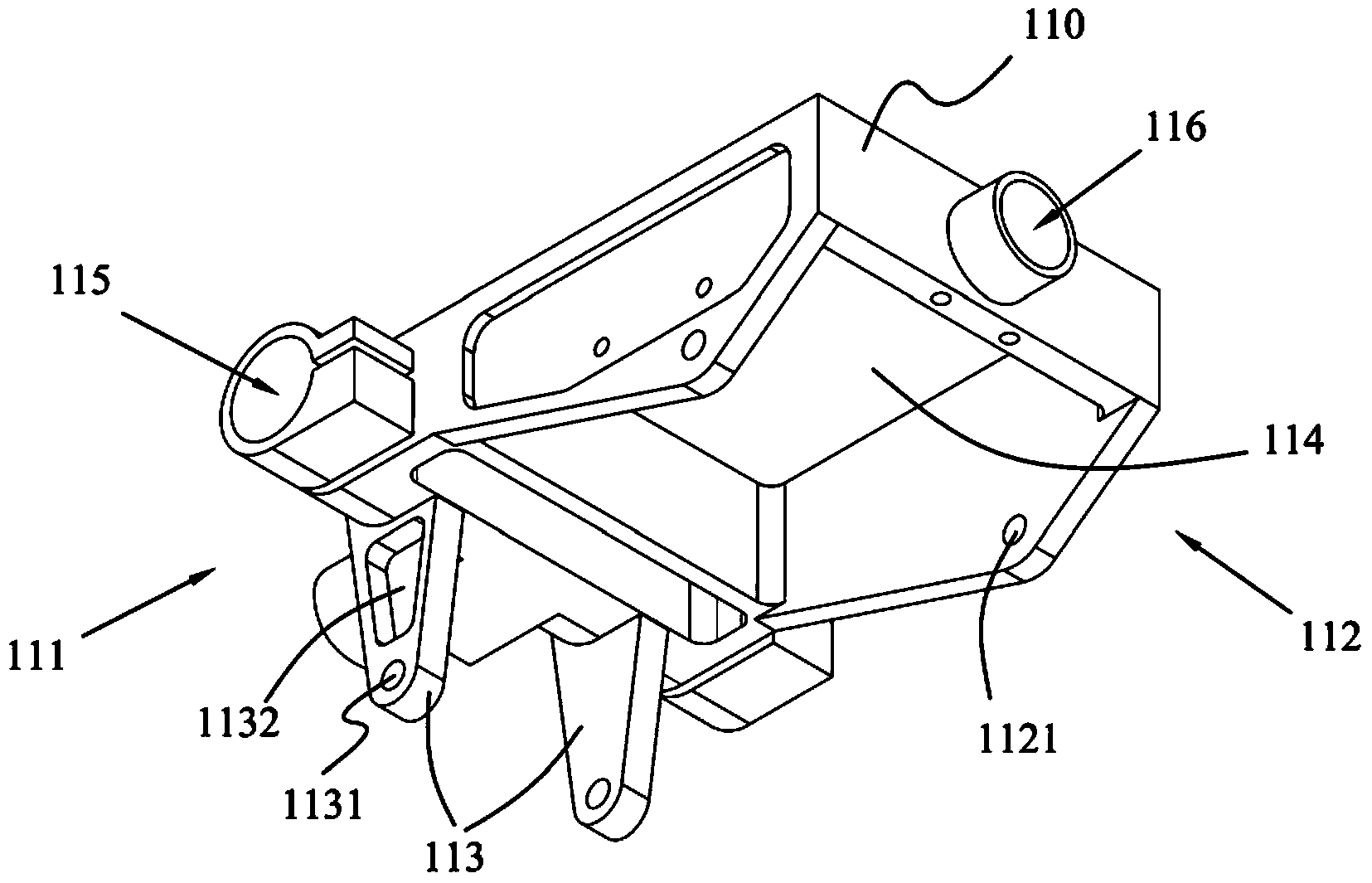
[0032] ginseng figure 2 As shown, the bracket frame 11 includes a main body 110, the main body 110 has a first end 111 and a second end 112, two brackets 113 extend from the bottom of the main body 110 at the position of the first end 111, and the bottom end of the bracket 113 is formed with The fi...


PUM


Abstract

The invention discloses a foldable landing gear. According to the landing gear, a support leg can be folded and unfolded; the support leg can be controlled to be folded in an aerial photographing process; the folded landing gear does not hinder a photographing lens, so that 360-degree all-dimensional smooth photographing of a camera can be ensured; a driving steering engine of the landing gear is used for transmitting power to a driving connection rod through a steering engine assembly; the steering engine assembly comprises a rudder angle and a rudder angle tank rotation shaft; the driving steering engine, the rudder angle and the rudder angle tank rotation shaft are products which are directly available in the market.

Description

technical field [0001] The application belongs to the field of multi-axis aircraft, in particular to a landing gear of an unmanned aircraft. Background technique [0002] Nowadays, multicopters are used in a wide range of applications, and they are mostly used for aerial photography among the people. A camera is installed on the multicopter, and the camera performs aerial shooting. In order to provide a stable shooting platform for the camera, more and more camera gimbals with stabilization functions are applied to multi-axis aircraft. Some of these movements are three-axis stabilized gimbals that allow the camera to rotate in three dimensions. [0003] The current multicopters use fixed landing gear. When the stabilized gimbal or camera platform rotates 360 degrees in the horizontal plane, the fixed landing gear will block the camera's line of sight, thereby affecting aerial shooting. Contents of the invention [0004] The purpose of the present invention is to provide...

Claims


Application Information

Patent Timeline
IPC IPC(8): B64C25/10B64C25/32
Inventor 杨华东许剑吴奇才
Owner 张家港锐泰智能科技有限公司
Why Eureka
Try Eureka