Embrasure structure on armored vehicle
A technology for shooting holes and armored vehicles, which is applied to armored vehicles, armored vehicles, motor vehicles, etc., can solve the problems of large openings in the shooting holes, unsatisfactory shooting effects, and inability to effectively bulletproof and waterproof, so as to reduce the shooting holes and improve the bulletproof effect. , the effect of smooth shooting
- Summary
- Abstract
- Description
- Claims
- Application Information
AI Technical Summary
Problems solved by technology
Method used
Image
Examples
Embodiment 1
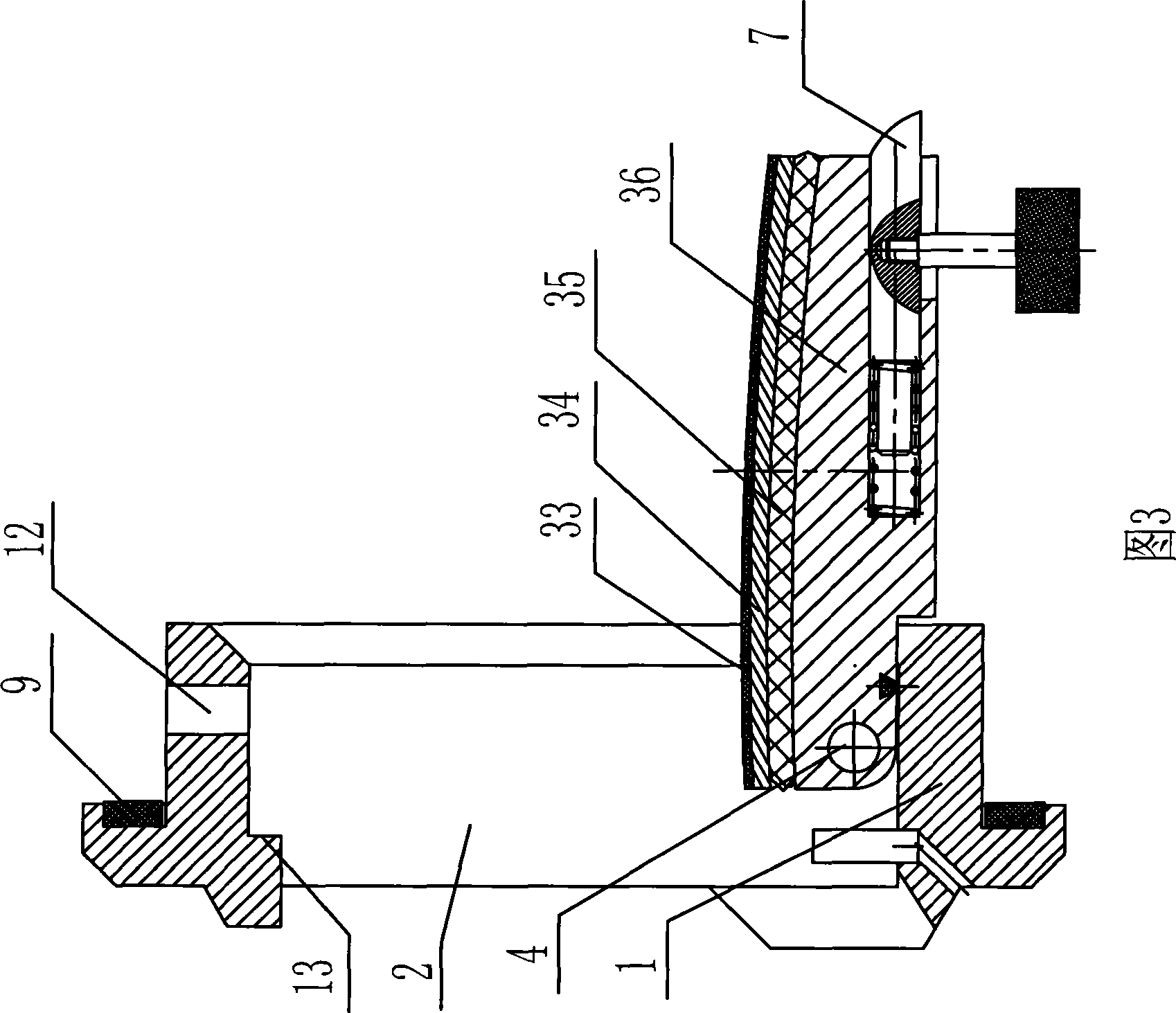
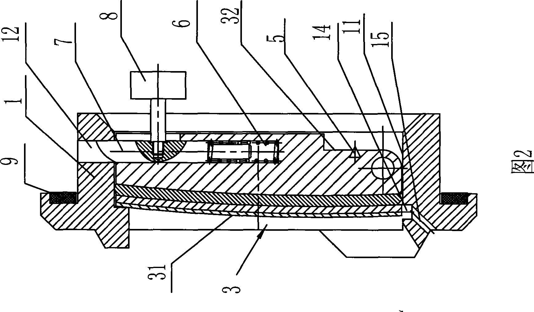
[0030] Such as figure 2 and 3As shown, the shooting hole structure on the armored vehicle includes a base 1 on which a shooting hole 2 is provided, and a movable baffle 3 that can block the shooting hole is provided in the shooting hole 2 . The lower end of the movable baffle 3 is fixed on the base 1 by the pin 4, the movable baffle 3 can rotate around the pin 4, when the movable baffle 3 rotates and stands up around the pin 4, the shooting hole 2 is covered, when the movable When the baffle plate 3 is put down, a support plane is formed, and the gun can be placed on the movable baffle plate 3 conveniently for shooting. The upper surface 31 of movable baffle 3 is an arc surface, and when movable baffle 3 was put down to support guns, the contact of its upper surface with guns made it more suitable for guns to be shelved on it. The bottom surface 32 of the movable baffle 3 is stepped, and a support plane 11 is provided on the inner surface where the lower end of the base 1 i...
Embodiment 2
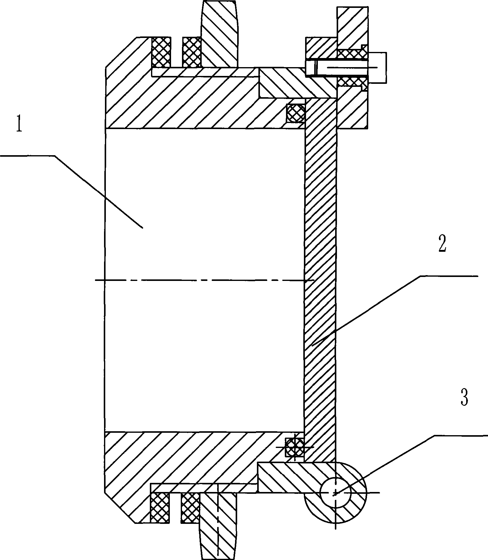
[0032] Such as Figure 4 and 5 As shown, the shooting hole structure on the armored vehicle includes a base 1. The base 1 includes a fixed frame body 16 and a movable cylinder body 17. The center of the movable cylinder body 17 is provided with a rotating shaft 18, and the rotating shaft 18 is fixed on the fixed frame body 16. Above, the movable cylinder 17 can rotate around the rotating shaft 18 . Be provided with shooting hole 2 on movable cylindrical body 17, the width of shooting hole 2 is 45mm, long 100mm, and the diameter of movable cylindrical body 17 is 95mm, and length is 120mm. In the shooting hole 2, a movable baffle 3 that can block the shooting hole is provided, and the movable baffle 3 is fixed on the inner bottom surface of the movable cylinder 17 by the pin shaft 4, and the lower bottom surface of the movable baffle 17 is stepped. Butt against the supporting plane of the inner bottom surface of the movable cylinder. The bottom surface of movable baffle 3 is ...
Embodiment 3
[0034] Such as Figure 9 As shown, the shooting hole structure on the armored vehicle includes a base, and the base includes a fixed frame 16 and a movable cylinder 17. The movable cylinder 17 rotates around the rotation axis, and the rotation axis is fixed on the fixed frame. A gasket 9 is provided at the junction of the frame body 16 to prevent water from entering the vehicle body. An observation window is arranged in the fixed frame 16 above the movable cylinder 17, and the observation window is arranged obliquely with the movable cylinder 17, that is, the vertical plane where the observation window is located is behind the vertical plane where the movable baffle 3 is located. Movable baffle 3 comprises rubber antiskid layer 33 successively from upper surface to bottom surface, and its thickness is 1.5mm; The thickness of bulletproof steel plate layer 34 is 8mm; . All the other are identical with embodiment 2.
PUM
 Abstract
Description
Claims
Application Information
 - R&D
- Intellectual Property
- Life Sciences
- Materials
- Tech Scout
- Unparalleled Data Quality
- Higher Quality Content
- 60% Fewer Hallucinations
Browse by: Latest US Patents, China's latest patents, Technical Efficacy Thesaurus, Application Domain, Technology Topic, Popular Technical Reports.
© 2025 PatSnap. All rights reserved.Legal|Privacy policy|Modern Slavery Act Transparency Statement|Sitemap|About US| Contact US: help@patsnap.com


