A control system for aerial photography rotorcraft
A technology for a rotorcraft and a control system, which is applied in the field of aerial photography rotorcraft control systems, can solve the problems of weak anti-gyro effect, poor anti-interference, and poor stability, and achieves strong anti-gyro effect, high integration, and good stability. Effect
- Summary
- Abstract
- Description
- Claims
- Application Information
AI Technical Summary
Problems solved by technology
Method used
Image
Examples
Embodiment 1
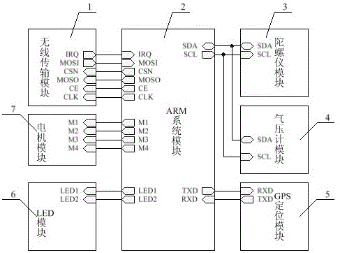
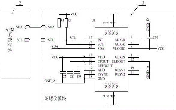
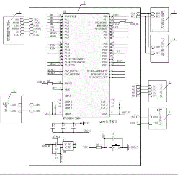
[0040] A control system for an aerial photography type rotorcraft. The aerial photography type rotorcraft described in this embodiment is an aerial photography type quadrotor aircraft, and the control system of the aerial photography type quadrotor aircraft is as follows: figure 1As shown, it includes a wireless transmission module 1 , an ARM system module 2 , a gyroscope module 3 , a barometer module 4 , a GPS positioning module 5 , an LED module 6 and a motor module 7 . The output terminals CSN, MOSO, CE and CLK of the ARM system module 2 are connected to the input terminals CSN, MOSO, CE and CLK of the wireless transmission module 1, and the input terminals IRQ and MOSI of the ARM system module 2 are connected to the output terminals of the wireless transmission module 1. IRQ and MOSI are connected correspondingly; the output terminal SCL of the ARM system module 2 is connected to the input terminal SCL of the gyroscope module 3, and the bidirectional input / output terminal ...
Embodiment 2
[0064] A control system for an aerial photography type rotorcraft. The aerial photography type rotorcraft described in this embodiment is an aerial photography type single rotor aircraft, and the aerial photography type single rotor aircraft control system except the following technical parameters, all the other are the same as embodiment 1:
[0065] The output terminal M1 of the ARM system module 2 is connected to the input terminal M1 of the motor module 7 .
[0066] The output terminal M1 of the chip U1 is connected to the input terminal M1 of the motor module 7 .
[0067] The motor module 7 is composed of a motor sub-module, and the motor sub-module is connected to the input terminal M1 of the motor module (7).
[0068] The input terminal M1 of the motor module 7 is connected to the output terminal M1 of the ARM system module 2 .
Embodiment 3
[0070] A control system for an aerial photography type rotorcraft. The aerial photography type rotorcraft described in this embodiment is an aerial photography type dual rotor aircraft, and the aerial photography type dual rotor aircraft control system is except the following technical parameters, all the other are the same as embodiment 1:
[0071] The output terminals M1 and M2 of the ARM system module 2 are correspondingly connected to the input terminals M1 and M2 of the motor module 7 .
[0072] The output terminals M1 and M2 of the chip U1 are correspondingly connected to the input terminals M1 and M2 of the motor module 7 .
[0073] The motor module 7 is composed of two mutually independent motor sub-modules, each motor sub-module is the same, and each motor sub-module is connected to the corresponding input terminals M1 and M2 of the motor module (7).
[0074] The input terminals M1 and M2 of the motor module 7 are correspondingly connected to the output terminals M1 ...
PUM
 Abstract
Description
Claims
Application Information
 - R&D
- Intellectual Property
- Life Sciences
- Materials
- Tech Scout
- Unparalleled Data Quality
- Higher Quality Content
- 60% Fewer Hallucinations
Browse by: Latest US Patents, China's latest patents, Technical Efficacy Thesaurus, Application Domain, Technology Topic, Popular Technical Reports.
© 2025 PatSnap. All rights reserved.Legal|Privacy policy|Modern Slavery Act Transparency Statement|Sitemap|About US| Contact US: help@patsnap.com


