Feeding device

A technology of feeding device and force applying device, applied in the direction of conveyor objects, transportation and packaging, etc., can solve the problem of low efficiency of feeding device, achieve the effect of improving work efficiency and speeding up processing progress

Inactive Publication Date: 2014-04-30
CHONGQING MING SHIELD ELECTROMAGNETIC VALVE
View PDF0 Cites 12 Cited by
  • Summary
  • Abstract
  • Description
  • Claims
  • Application Information

AI Technical Summary

Problems solved by technology

[0003] The invention provides a feeding device to solve the problem of low efficiency of the existing feeding device

Method used


Image

  • Feeding device

Examples


Embodiment Construction

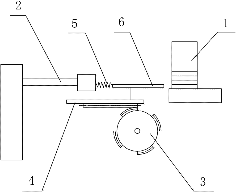
[0010] Such as figure 1 As shown, a feeding device in this embodiment includes a push rod 1, a base 2, a toothless gear 3 as a force applying device, a transmission rod 4 with a rack, and a feeding box 6 containing materials, wherein, There are multiple tooth-missing segments evenly distributed on the tooth-missing gear 3, the tooth-missing gear 3 is driven by a motor, the tooth-missing gear 3 meshes with the rack on the transmission rod 4, the transmission rod 4 is connected with the push rod 1, and the push rod 1 is reset The spring 5 is connected to the base 2 . The push rod 1 needs to reciprocate left and right to realize the delivery of the material in the feeding box 6 .

[0011] When working, the tooth-missing gear 3 rotates under the drive of the motor. When the gear segment meshes with the toothed segment, the gear 3 pushes the push rod 1 to feed through the transmission rod 4; when it enters the tooth-missing segment, the gear 3 does not contact the rack. The push ...


PUM


Abstract

The invention discloses a feeding device. The feeding device comprises a push rod, a base, a tooth missing gear as a force application device, and a drive rod with a rack, wherein a plurality of tooth missing sections are arranged on the tooth missing gear, the tooth missing gear is driven by a motor and engaged with the rack on the drive rod, the drive rod is connected with the push rod, and the push rod is connected to the base through a return spring. The feeding device is capable of realizing multiple reciprocating actions by virtue of the plurality of tooth missing sections as the gear rotates by one circle, and therefore, the working efficiency of the feeding device is improved and the processing progress is accelerated.

Description

technical field [0001] The present invention belongs to the technical field of conveying devices. Background technique [0002] At present, the feeding device needs the push rod to reciprocate, and the planar four-bar linkage mechanism is usually used, but there is a problem of low efficiency in this structure. The crank in the four-bar mechanism makes a 360° turnover to realize the push rod ( The pendulum in a four-bar linkage) moves back and forth. The low efficiency of the feeding mechanism will also directly affect the subsequent operations, resulting in slower processing progress. Contents of the invention [0003] The invention provides a feeding device to solve the problem of low efficiency of the existing feeding device. [0004] In order to solve the above-mentioned technical problems, the present invention provides the following technical solutions: A feeding device, comprising a push rod, a base, a tooth-missing gear as a force applying device, and a drive rod...

Claims


Application Information

Patent Timeline
Patent Type & Authority Applications(China)
IPC IPC(8): B65G47/82
Inventor 姜静慧
Owner CHONGQING MING SHIELD ELECTROMAGNETIC VALVE
Why Eureka
Try Eureka