Gun sight

A sight and lens barrel technology, applied in the field of scope, can solve the problems of low aiming accuracy and inability to guarantee shooting accuracy, and achieve the effects of improving aiming accuracy, improving comfort, and ensuring accuracy

Inactive Publication Date: 2014-04-30
NANTONG GUANGXING PNEUMATIC EQUIP
View PDF4 Cites 0 Cited by
  • Summary
  • Abstract
  • Description
  • Claims
  • Application Information

AI Technical Summary

Problems solved by technology

The sight cannot bring the objective lens close to the barrel at close range, so the aiming accuracy is not high, and the shooting accuracy cannot be guaranteed

Method used


Image

  • Gun sight
  • Gun sight
  • Gun sight

Examples


Embodiment Construction

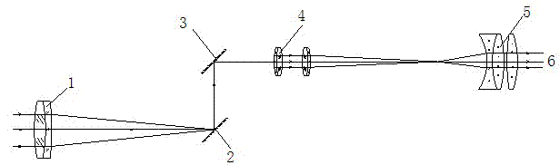
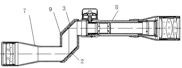
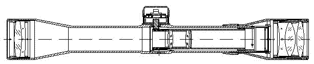
[0012] Below in conjunction with accompanying drawing, the present invention is described in detail: as figure 1 , figure 2 Shown, the scope of the present invention, eyepiece barrel comprises objective lens fixed lens barrel 7, eyepiece fixed lens barrel 8 and connecting lens barrel 9, connecting lens barrel 9 connects objective lens fixed lens barrel 7 and eyepiece fixed lens barrel 8, objective lens fixed lens barrel 7 It is parallel to and not on the same axis with the eyepiece fixed lens barrel 8, and the two form a Z-shape with the connecting lens barrel 9. The objective lens 1 is installed at the end of the objective lens fixed lens barrel 7, the eyepiece 5 is installed at the end of the eyepiece fixed lens barrel 8, and the turning mirror 4 is installed inside the eyepiece fixed lens barrel 8. Two parallel and opposite first reflecting mirrors 2 and second reflecting mirrors 3 are installed in the connecting lens barrel 9, the first reflecting mirror 2 is arranged o...


PUM


Abstract

The invention discloses a gun sight comprising a barrel, an eyepiece and an objective. The eyepiece and the objective are disposed at two ends of the barrel. A diversion lens is further disposed in the middle of the barrel. The barrel comprises an eyepiece fixing barrel, an objective fixing barrel and a connecting barrel. The eyepiece is disposed at one end of the eyepiece fixing barrel. The diversion lens is disposed in the eyepiece fixing barrel. The objective is disposed at one end of the objective fixing barrel. The connecting barrel is connected between the eyepiece fixing barrel and the objective fixing barrel. A first axis of the eyepiece fixing barrel and a second axis of the objective fixing sleeve are parallel and spaced at a certain interval. A pair of parallel reflectors is disposed in the connecting barrel. Compared to the prior art, the gun slight has the advantages that the pair of reflectors is ingeniously utilized, the original linear barrel is modified into a Z-shaped combination of two small barrels having different axes, and accordingly the objective can be pressed close to a gun barrel without changing the position of the eyepiece, aiming precision is improved and shooting precision is guaranteed.

Description

Technical field: [0001] The invention relates to the technical field of electric devices, in particular to a scope. Background technique: [0002] The eyepiece barrel of existing scope is a straight tube, and eyepiece, object lens and turning lens etc. are installed in the straight tube, see image 3 . The sight cannot bring the objective lens close to the barrel at close range, so the aiming accuracy is not high, and the shooting accuracy cannot be guaranteed. Invention content: [0003] The technical problem to be solved by the present invention is to provide a sight that can put the eyepiece close to the gun barrel, thereby improving the aiming accuracy and ensuring the shooting accuracy. [0004] In order to solve the problems of the technologies described above, the technical solution adopted in the present invention is: [0005] A sighting scope, comprising a lens barrel and eyepieces and objective lenses arranged at both ends of the lens barrel, and a steering...

Claims


Application Information

Patent Timeline
IPC IPC(8): F41G1/14
Inventor 高雪峰唐明智
Owner NANTONG GUANGXING PNEUMATIC EQUIP
Why Eureka
Try Eureka