
A rifle butt conversion mechanism

A technology for gun stocks and rifles, applied in the field of firearms, can solve the problems of rifle center of gravity lateral deviation, incompleteness, affecting shooting accuracy, etc., to achieve the effect of ensuring shooting accuracy and avoiding lateral deviation

Inactive Publication Date: 2020-02-07
SHENYANG LIGONG UNIV
View PDF10 Cites 0 Cited by
  • Summary
  • Abstract
  • Description
  • Claims
  • Application Information

AI Technical Summary

Problems solved by technology

However, since the buttstock is folded and located on the side of the rear receiver of the rifle, this will cause a lateral shift in the center of gravity of the rifle, which will affect the shooting accuracy to a certain extent
In addition, when the buttstock in the folded and converted form is in the non-folded state, the position of the buttstock in the length direction of the rifle is not adjustable, so it cannot better adapt to the stature of different soldiers.
[0006] For the telescopic conversion form, the buttstock is retracted into the rear receiver of the rifle to achieve the "no support" state, but this "no support" state is not complete, and some buttstocks will still remain outside the rear receiver of the rifle , so this kind of butt conversion form cannot be completely "no support"

Method used


Image

  • A rifle butt conversion mechanism
  • A rifle butt conversion mechanism
  • A rifle butt conversion mechanism

Examples


Embodiment Construction

[0023] The present invention will be further described in detail below in conjunction with the accompanying drawings and specific embodiments.

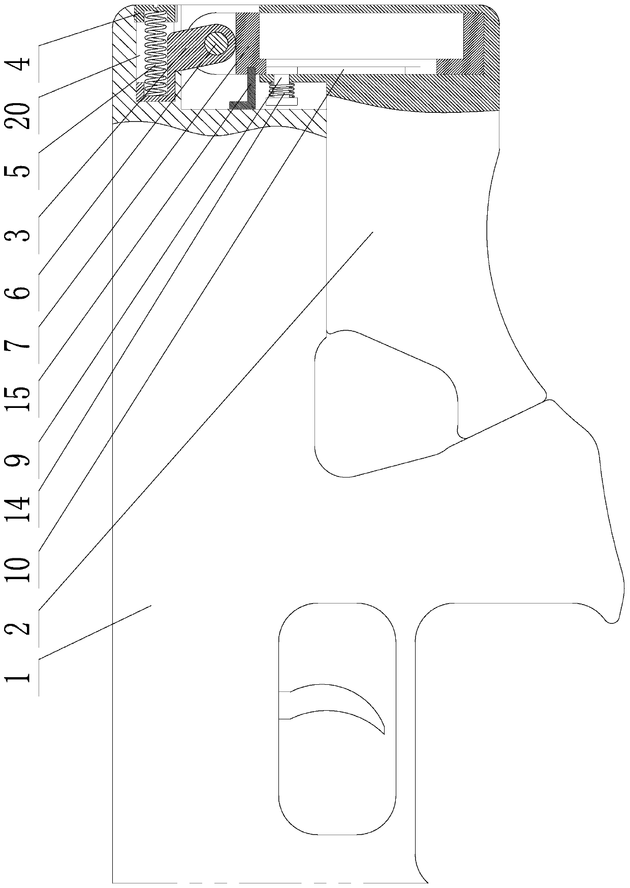
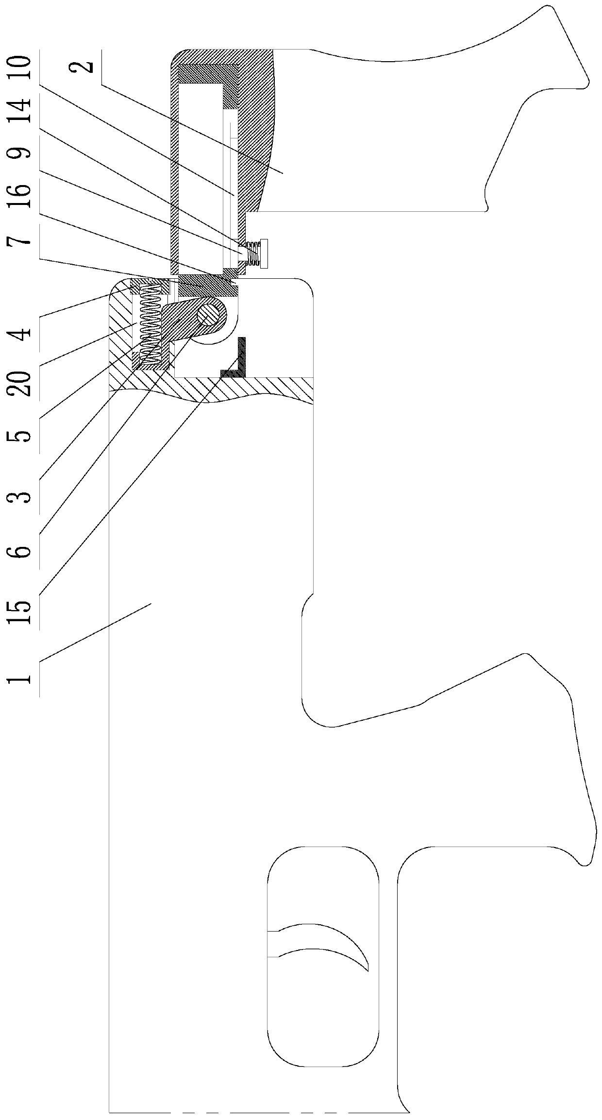
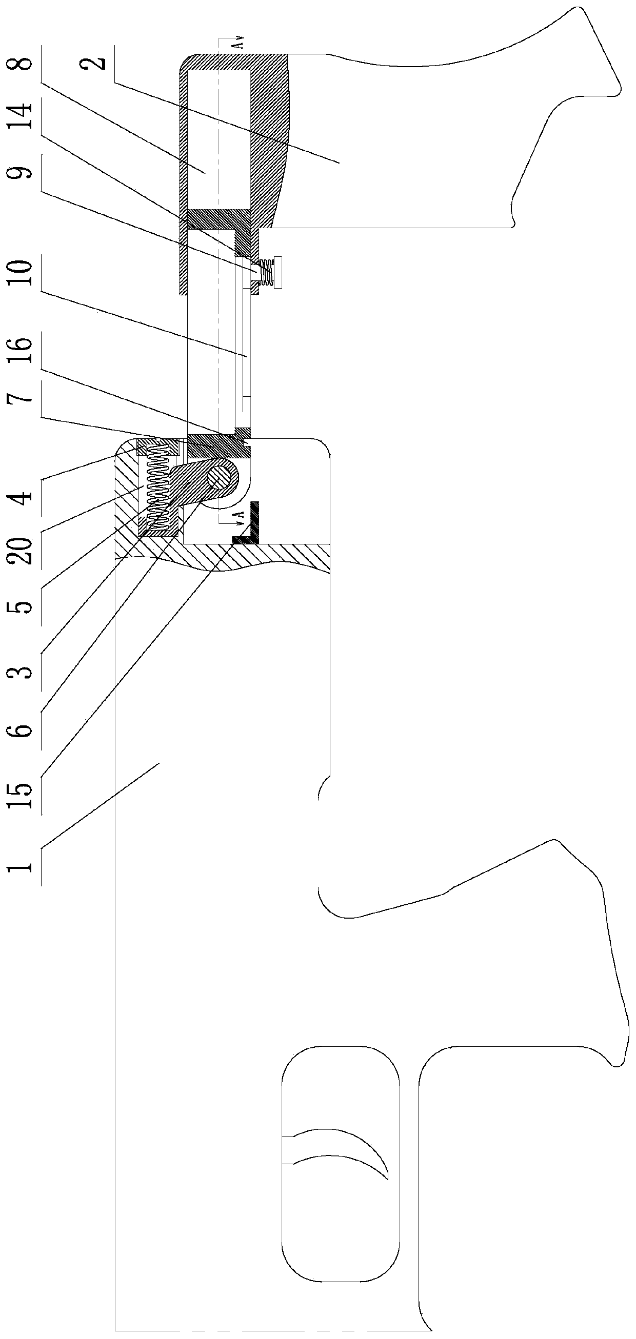
[0024] Such as Figure 1-8 As shown, a rifle butt conversion mechanism includes rifle rear receiver 1, butt 2, hinge lug seat 3, hinge lug seat sealing screw 4, hinge lug seat supporting thrust spring 5, hinge shaft 6 and swing rod 7 ; The rear part of the rifle rear receiver 1 is provided with a hinge ear seat mounting hole 20, the hinge ear seat 3 is located in the hinge ear seat installation hole 20, and the hinge ear seat blocking screw 4 is fixed on the hinge ear At the opening of the seat mounting hole 20, the hinge ear seat support thrust spring 5 is arranged between the hinge ear seat 3 and the hinge ear seat plugging screw 4, and the two ends of the hinge ear seat support thrust spring 5 respectively lean against the hinge. On the ear seat 3 and the hinge ear seat plugging screw 4, the hinge ear seat 3 has an axial movement ...


PUM


Abstract

A rifle gunstock switching mechanism comprises a rifle rear cartridge receiver, a gunstock, a hinged lug base, a blocking bolt, a thrusting spring, a hinged shaft and a swinging rod. The rear part ofthe rifle rear cartridge receiver is provided with a hinged lug base installation hole, the hinged lug base is located in the hinged lug base installation hole and can axially move in the hole, the blocking bolt is fixedly arranged in a hole opening, and the thrusting spring is arranged between the blocking bolt and the hinged lug base. The swinging rod is connected with the hinged lug base through the hinged shaft, the gunstock is internally provided with a swinging rod insertion hole, the swinging rod is inserted into the hole, and the gunstock can do linear movement along the swinging rod.The swinging rod is a hollow rod body, and a position adjusting and positioning structure is arranged between the gunstock and the swinging rod. The position adjusting and positioning structure comprises a special-shaped positioning pin and a guide sliding groove, the guide sliding groove is formed in the swinging rod body, the special-shaped positioning pin is composed of a cylindrical rod, a finger pressing disk and a positioning disk, the two ends of the guide sliding groove are provided with positioning disk limiting holes, the positioning disk is located on the inner side of the swingingrod body, the cylindrical rod penetrates through the guide sliding groove and a gunstock shell, the finger pressing disk is located on the outer side of the gunstock shell, and a reset spring is arranged between the finger pressing disk and the gunstock shell.

Description

technical field [0001] The invention belongs to the technical field of firearms, in particular to a rifle butt conversion mechanism. Background technique [0002] As one of the basic components of a rifle, the buttstock has two main functions. The first function is to hold the shoulder against the shoulder when aiming to improve shooting accuracy, and the second function is to reduce the impact of shooting recoil on soldiers. [0003] The butt is located at the rear of the rear receiver of the rifle. The early butt usually belongs to the structural extension of the rear receiver of the rifle, that is, the butt and the rear receiver of the rifle are manufactured as a whole; in addition, the butts of some rifles are manufactured separately. During the rifle assembly stage, the buttstock is fixedly connected to the rifle rear receiver. However, no matter which of the above-mentioned forms, the buttstock and the rear receiver of the rifle are not adjustable, so this fixed butts...

Claims


Application Information

Patent Timeline
Patent Type & Authority Patents(China)
IPC IPC(8): F41C23/14
CPCF41C23/14
Inventor 胡明李回滨林中鹰陈青华
Owner SHENYANG LIGONG UNIV
Learn More