
A cathode structure of a proton exchange membrane fuel cell

A proton exchange membrane and fuel cell technology, applied in battery electrodes, structural parts, circuits, etc., can solve the problems of oxygen concentration reduction, failure to reach, hinder oxygen diffusion, etc., achieve uniform distribution of oxygen concentration, improve distribution state, increase The effect of work performance

Inactive Publication Date: 2016-08-17
TIANJIN UNIV
View PDF5 Cites 0 Cited by
  • Summary
  • Abstract
  • Description
  • Claims
  • Application Information

AI Technical Summary

Problems solved by technology

[0009] Generally speaking, the voltage of an ideal proton exchange membrane fuel cell is about 1.2V, but in actual use, due to the four decisive and irreversible factors of activation loss, ohmic loss, mass transfer loss and internal short-circuit current Exist, often not reach this value
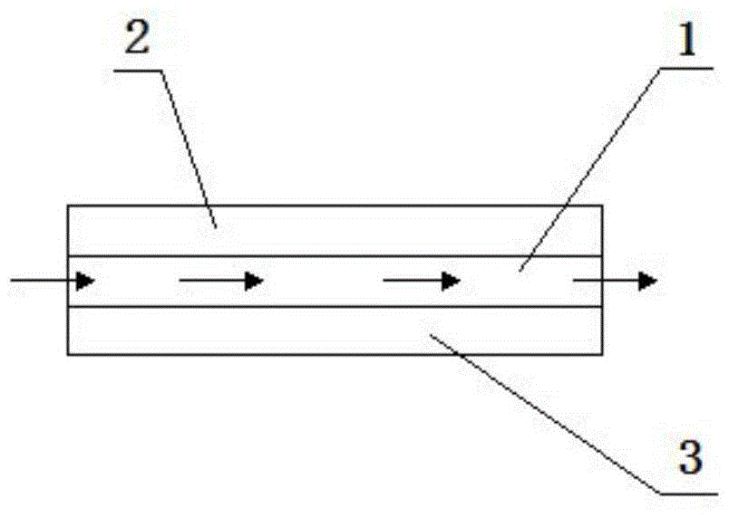
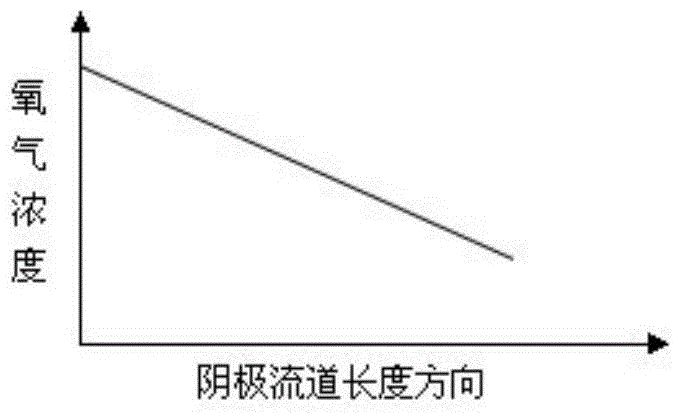
[0010] And because the concentration of oxygen will directly affect the electrochemical reaction rate inside the PEM fuel cell[1], when air is used as the oxidant to provide the oxygen required for the fuel cell cathode reaction, the chemical reaction will naturally Consuming part of the oxygen will naturally reduce the oxygen concentration in the direction of the cathode, resulting in uneven distribution of the reaction gas concentration
According to the Tafel formula, for the reduction reaction of oxygen, the local current density is proportional to the oxygen concentration (oxygen partial pressure) participating in the reaction [2], so the uneven distribution of oxygen directly hinders the improvement of fuel cell performance
[0011] On the other hand, since the water generated by the cathode reaction will gradually accumulate in the flow channel, it is easy to block the gaps in the gas diffusion layer, which directly hinders the diffusion of oxygen, and further aggravates the reaction resistance downstream of the fuel cell.

Method used


Image

  • A cathode structure of a proton exchange membrane fuel cell
  • A cathode structure of a proton exchange membrane fuel cell
  • A cathode structure of a proton exchange membrane fuel cell

Examples


Embodiment 1

[0032] Figure 5 , Figure 6 The structure of a flow field plate in the embodiment of the present invention is illustrated respectively in the form of a front view and a top view.

[0033] see Figure 5 , the flow field plate 2 in this embodiment is arranged as a symmetrical structure between the A surface and the B surface, the B surface directly contacts the membrane electrode 3 and there are several flow channels 1 evenly spaced thereon, the A The surface is symmetrical to the B surface, and the grooves 22 corresponding to the position of the flow channel 1 are arranged evenly on it, and the flow channel 1 and the groove 22 are connected through several round holes 23; see Figure 6 A plurality of the circular holes 23 are arranged in order of diameter on the flow channel 1 and the groove 22 connected therewith.

[0034] In this embodiment, the cathode air enters the groove 22 of the flow field plate 2 on the A side through the air inlet, then passes through the circular...

Embodiment 2

[0037] Figure 7 The structure of another flow field plate in the embodiment of the present invention is illustrated.

[0038] see Figure 7 , the cross-sectional structure of the flow field plate 2 in this embodiment is a trapezoidal tooth shape, and the flow field plate 2 is also provided with two sides A and B, but the B side directly contacts the membrane electrode 3 and is concave toward A The trapezoidal tooth shape of the surface forms the flow channel 1, and the trapezoidal tooth shape of the A surface forms a groove 22 with its concave to the B surface. The flow channel 1 is adjacent to the grooves 22 on both sides, and passes through several The circular holes 23 are connected; several circular holes 23 are arranged on the flow channel 1 and the groove 22 connected therewith in the order of gradually increasing diameter along the direction of cathode air delivery.

[0039]In this embodiment, the cathode air enters the groove 22 of the flow field plate 2 on the A si...


PUM


Abstract

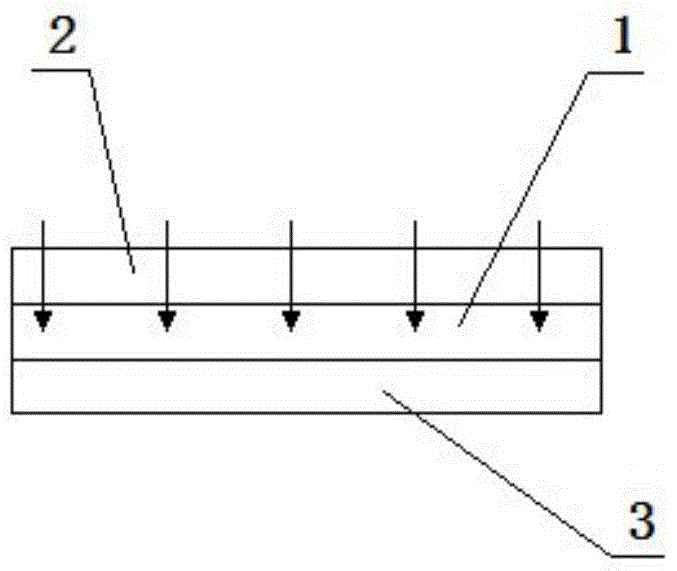
The invention discloses a cathode structure of a proton exchange membrane fuel cell, which comprises a flow field plate, and a membrane electrode arranged below the flow field plate, wherein flow channels are arranged on one surface, in contact with the membrane electrode, of the flow field plate, and grooves are formed in the other surface of the flow field plate; the flow channels are communicated with the grooves through a plurality of round holes; the round holes are formed in the flow channels and the grooves all communicated with the round holes in the order of gradual increasing of the diameter in the cathode air conveying direction. According to the invention, through changing the direction of air entering the cathode flow channels, and the convection mode of cathode air and a gas diffusion layer in the membrane electrode, the diffusivity of air on a catalyst layer of the membrane electrode is enhanced; compared with the prior art, the cathode structure has the advantages that the concentration of oxygen distributed in any position of the cathode flow channels is uniform, the distribution of partial current is improved, and the working performance of a cell is effectively improved.

Description

technical field [0001] The invention relates to a proton exchange membrane fuel cell, more specifically, the invention relates to a technical improvement on the existing cathode structure of the proton exchange membrane fuel cell. Background technique [0002] Traditional fossil energy, while making great changes in human society, has also brought serious environmental pollution problems. In order to solve this problem, relevant research at home and abroad has been increasing in recent years. [0003] The proton exchange membrane fuel cell that emerged at the historic moment uses hydrogen and oxygen as raw materials. Its biggest feature is no pollution, and has the advantages of low operating temperature, high energy density, fast start-up, and low noise. It is expected to be widely used in portable power supplies , electric vehicles and other fields, its market prospect is considerable. [0004] figure 1 The cathode structure of the existing proton exchange membrane fuel...

Claims


Application Information

Patent Timeline
Patent Type & Authority Patents(China)
IPC IPC(8): H01M4/86
CPCH01M4/8626Y02E60/50
Inventor 王世学齐贺邵光威
Owner TIANJIN UNIV
Learn More