Power cabinet capable of testing line head joint strength
A technology of connection strength and power cabinet, applied in the field of power cabinet, can solve the problems of inaccurate test and large error of test result, and achieve the effect of accurate result, simple test and convenient follow-up maintenance
- Summary
- Abstract
- Description
- Claims
- Application Information
AI Technical Summary
Problems solved by technology
Method used
Image

Examples
Embodiment 1
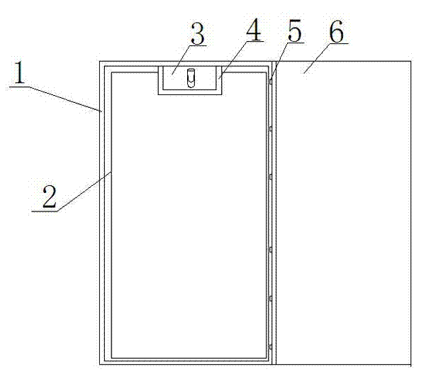
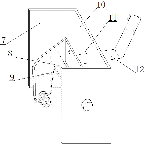
[0017] see Figure 1-Figure 3 , a power cabinet that can test the connection strength of wire ends, including a square cabinet body 1 and a cabinet body cover 6, the cabinet body cover 6 is rotatably connected to the side end of the square cabinet body 1 through a plurality of hinges 5, and the inside of the square cabinet body 1 The upper end is provided with a fixed plate 4, and the fixed plate 4 is fixed with a wire end connection strength test device 3, and the thread end connection strength test device 3 includes a connecting plate 10, and the connecting plate 10 is provided with a vertical groove 11, and the two ends of the connecting plate 10 are vertical Two parallel mounting plates 7 connected to the fixed plate 4 are connected, a rotating shaft 8 is connected between the two mounting plates 7, a rotating plate 9 is connected to the rotating shaft 8, and a roller 16 is arranged on the rotating plate 9. A wrench 12 passing through the vertical slot 11 is also connected...
Embodiment 2
[0021] In this embodiment, the following structure is added on the basis of Embodiment 1: a layer of insulation layer 2 is arranged inside the square cabinet body 1 .
[0022] In this embodiment, in order to prevent the use of electrical components inside the power cabinet from being affected by low temperature, an insulating layer 2 is provided inside the square cabinet body 1, so that the power cabinet can be used normally in a lower temperature environment.
Embodiment 3
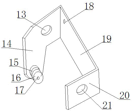
[0024] This embodiment optimizes the rotating plate on the basis of embodiment 1 or embodiment 2, specifically: the rotating plate 9 includes a linkage plate 19 and a straight plate 20 and a folded plate 14 connected to the two ends of the linkage plate 19; the straight plate 20 A straight plate mounting hole 21 is provided on the top; a folding plate mounting hole 13 is provided on the folding plate 14 , and the lower end of the folding plate 14 extends to form a mounting portion, and the mounting portion is connected to the roller 16 through a rotating rod 17 .
[0025] In this embodiment, the rotating shaft 8 passes through the straight plate mounting hole 21 and the folding plate mounting hole 13 to fix the rotating plate 9 as a whole between the two mounting plates 7, the rotating plate 9 can rotate around the rotating shaft 8, and the linkage plate 19 is used to drive The straight plate 20 and the folding plate 14 rotate, so that the roller 16 can be driven to rotate. Whe...
PUM
 Abstract
Description
Claims
Application Information
 - R&D Engineer
- R&D Manager
- IP Professional
- Industry Leading Data Capabilities
- Powerful AI technology
- Patent DNA Extraction
Browse by: Latest US Patents, China's latest patents, Technical Efficacy Thesaurus, Application Domain, Technology Topic.
© 2024 PatSnap. All rights reserved.Legal|Privacy policy|Modern Slavery Act Transparency Statement|Sitemap