
Locomotive positioning method suitable for wireless switching locomotive signal and monitoring system

A technology for shunting locomotives and monitoring systems, applied in the field of rail transit, can solve problems such as inconvenient care and maintenance, inability to locate locomotives, and high investment costs, so as to reduce equipment misjudgments or functional failures, and solve location information errors Larger and lower equipment production costs

Active Publication Date: 2014-06-18
CHINA ACADEMY OF RAILWAY SCI CORP LTD +3
View PDF1 Cites 23 Cited by
  • Summary
  • Abstract
  • Description
  • Claims
  • Application Information

AI Technical Summary

Problems solved by technology

[0007] However, when using transponders for locomotive positioning, there are the following defects: the equipment using this positioning method is complex, there are many components, the amount of construction and maintenance is large, and the investment cost is high
The cost of the transponder and related equipment accounts for about 30% of the total cost of the equipment, and the investment cost is relatively large; since the transponder is installed on the outdoor line, it is inconvenient to care and maintain, and loss and damage occur from time to time. The technical solution is highly dependent on the balise. When the balise is lost or damaged, the locomotive cannot be located when it enters the station; the position information contained in the balise varies according to the different situations of each station. The technician writes in the on-site installation, and at the same time, the transponders with different information must be installed in different locations
Due to the large amount of transponders installed in the station, it is inevitable that there will be errors in information writing or wrong installation positions during the process. If they are not discovered in time, it will cause the locomotive to enter the station and cannot be located, and more seriously, it may cause locomotives to be positioned incorrectly. occur

Method used


Image

  • Locomotive positioning method suitable for wireless switching locomotive signal and monitoring system
  • Locomotive positioning method suitable for wireless switching locomotive signal and monitoring system
  • Locomotive positioning method suitable for wireless switching locomotive signal and monitoring system

Examples


Embodiment 1

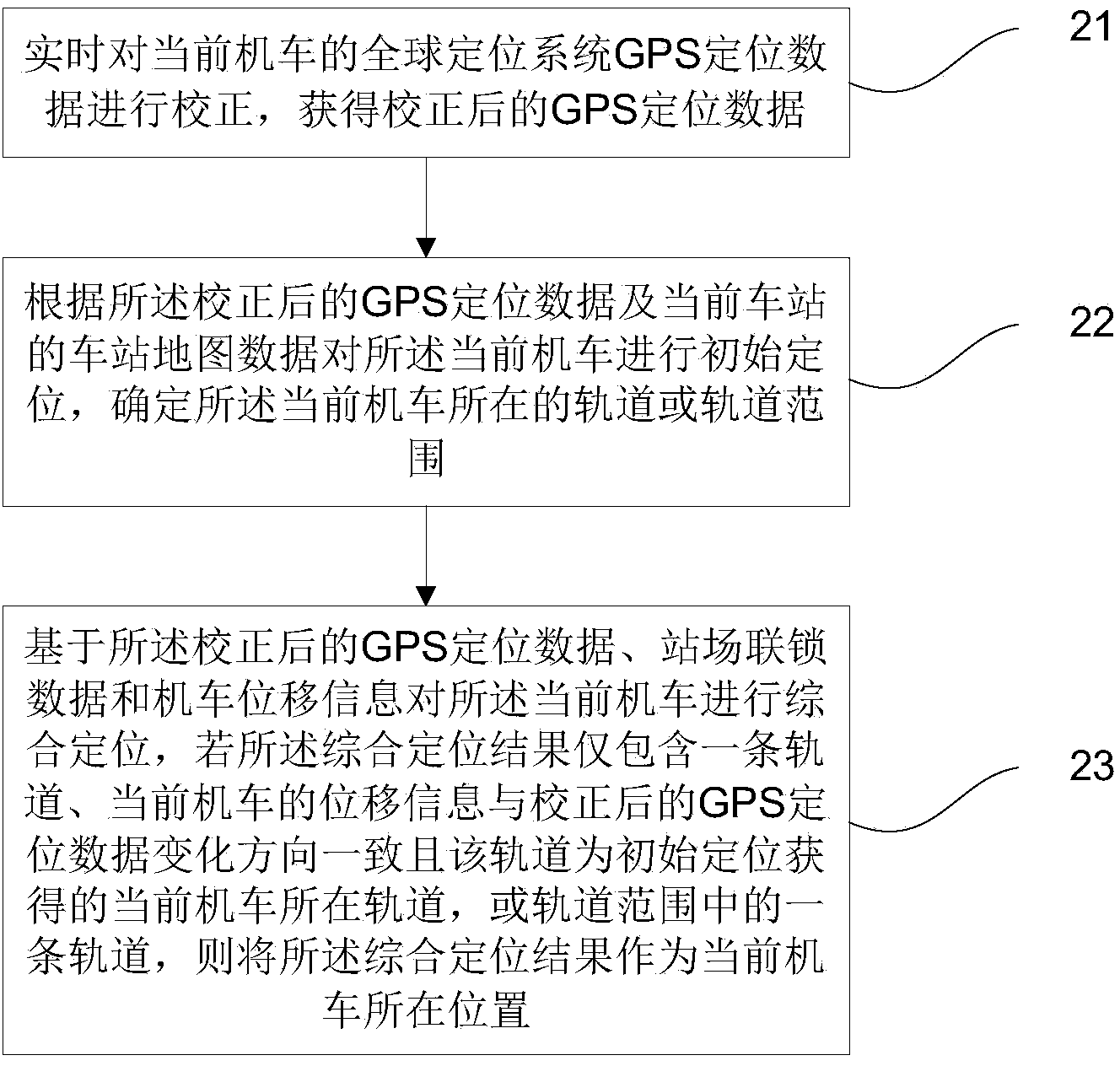
[0025] figure 2 It is a flowchart of a locomotive positioning method suitable for a wireless shunting locomotive signal and monitoring system provided by Embodiment 1 of the present invention. Such as figure 2 As shown, the method mainly includes the following steps:

[0026] Step 21, correcting the GPS positioning data of the current locomotive in real time to obtain the corrected GPS positioning data.

[0027] In the embodiment of the present invention, a filter (α-β filter) is used to filter the calculated distance from visible satellites and the difference between the measured values ​​containing errors and calculate the deviation to obtain differential data; and then use the The differential data corrects the GPS positioning data of the locomotive; obtains the corrected GPS positioning data (for example, latitude and longitude).

[0028] Step 22: Initially locate the current locomotive according to the corrected GPS positioning data and the station map data of the cu...

Embodiment 2

[0051] In order to facilitate understanding of the present invention, below in conjunction with Figure 3-7 The present invention is further introduced.

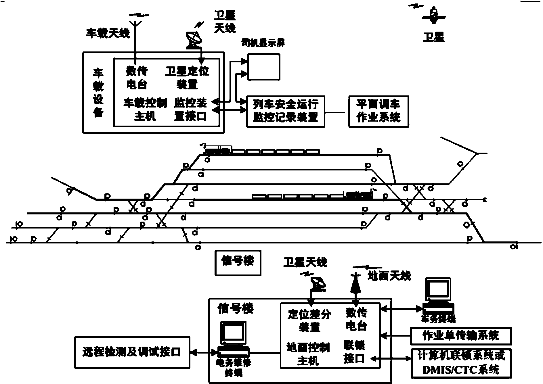
[0052] The solution of the embodiment of the present invention can be applied to the STP system, such as image 3 As shown, the ground equipment has added a positioning differential device, and the vehicle equipment has added a satellite positioning device.

[0053] Among them, the vehicle-mounted satellite positioning device for receiving GPS signals in the vehicle-mounted equipment has the following components: Figure 4 As shown, the vehicle-mounted satellite positioning device on the locomotive is composed of a GPS board and an embedded processor. The GPS board can be a high-precision OEM board. The single-point positioning accuracy can reach 1.8m, and the pseudo-range differential positioning accuracy can reach 0.45m. When the vehicle-mounted host computer receives the differential data broadcast by the ground equipm...


PUM


Abstract

The invention discloses a locomotive positioning method suitable for a wireless switching locomotive signal and monitoring system. The method includes the steps that GPS positioning data of a current locomotive are corrected in real time, and then the corrected GPS positioning data are acquired; according to the corrected GPS positioning data and station map data of a current station, the current locomotive is initially positioned, and a track where the current locomotive is located or the track range of the current locomotive is determined; based on the corrected GPS positioning data, station yard interlocking data and locomotive displacement information, the current locomotive is comprehensively positioned, if a comprehensive positioning result shows that only one track is contained, the displacement information of the current locomotive is consistent with the change direction of the corrected GPS positioning data, and the track is the acquired track where the current locomotive is located in the initial positioning process or one track within the track range, the comprehensive positioning result is used for showing the position where the current locomotive is located. By the adoption of the method, the equipment structure is simplified, and equipment cost is reduced.

Description

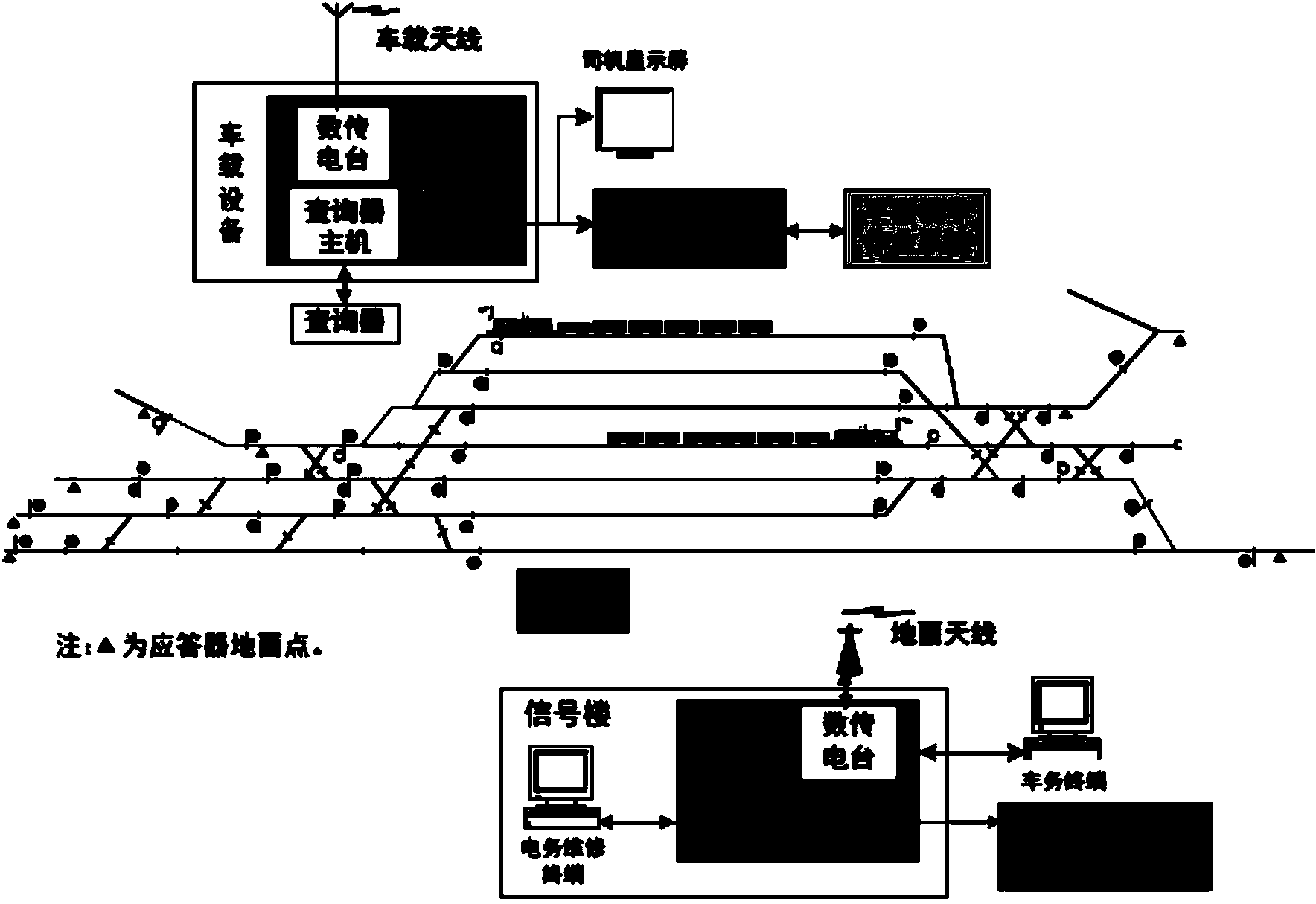
technical field [0001] The invention relates to the technical field of rail transit, in particular to a locomotive positioning method suitable for a wireless shunting locomotive signal and monitoring system. Background technique [0002] The wireless shunting locomotive signal and monitoring system (STP system for short) is a computer integrated control system. The system adopts wireless digital transmission technology, locomotive intelligent tracking technology, passive transponder positioning technology and locomotive safety protection control technology. Comprehensive safety protection is carried out for the shunting operation, which can effectively prevent the occurrence of common accidents such as running the blue light of the shunting locomotive, squeezing the switch, and exceeding the speed limit. Secondly, the system can realize the real-time display of shunting signal, shunting approach, shunting front protection distance, station graphics and other information on t...

Claims


Application Information

Patent Timeline
Patent Type & Authority Applications(China)
IPC IPC(8): G01S19/50
CPCG01S19/50
Inventor 曹桂均杨华昌冯军程君闫石任宛星韩波赵阳张弘志李铁尹得胜栾德杰王浩然李继东陈尚斌林炳跃唐汇东秦朝亮赵小军黄天天马金鑫王迪菲曹子昱王新勇张为
Owner CHINA ACADEMY OF RAILWAY SCI CORP LTD
Learn More