Odometer method and device for sports equipment

A technology of sports equipment and odometer, which is applied in the direction of measuring devices, instruments, surveying and navigation, etc., can solve the problems of high error and low odometer accuracy, and achieve the effect of suppressing accumulated errors and good adaptability

Active Publication Date: 2017-09-08
HANGZHOU JIAZHI TECH CO LTD
View PDF1 Cites 22 Cited by
  • Summary
  • Abstract
  • Description
  • Claims
  • Application Information

AI Technical Summary

Problems solved by technology

[0004] In order to solve the defects of low precision and high error of the odometer in the prior art, the present invention provides an odometer method and an odometer device for sports equipment

Method used


Image

  • Odometer method and device for sports equipment
  • Odometer method and device for sports equipment
  • Odometer method and device for sports equipment

Examples


Embodiment 1

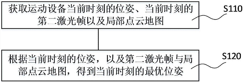
[0050] figure 1 is a schematic flowchart of the odometer method provided in this embodiment.

[0051] The devices in the application scene of this method include sports equipment, computing equipment, and laser scanning equipment and physical mileage equipment set on the sports equipment. Sports equipment can be mobile robots, sweeping robots, robotic toys, or smart homes that need to be moved and positioned indoors. Computing equipment is used to calculate various data, and the data sources are sports equipment, laser scanning equipment, physical mileage equipment, etc. The physical mileage device is used to detect and obtain the motion data of the sports equipment to estimate the change in the pose of the sports equipment over time, including the position change, angle change, etc., and is generally set on the sports equipment, such as a code wheel, other photoelectric encoders, or Other sensing elements that measure the displacement of moving equipment over a period of ti...

Embodiment 2

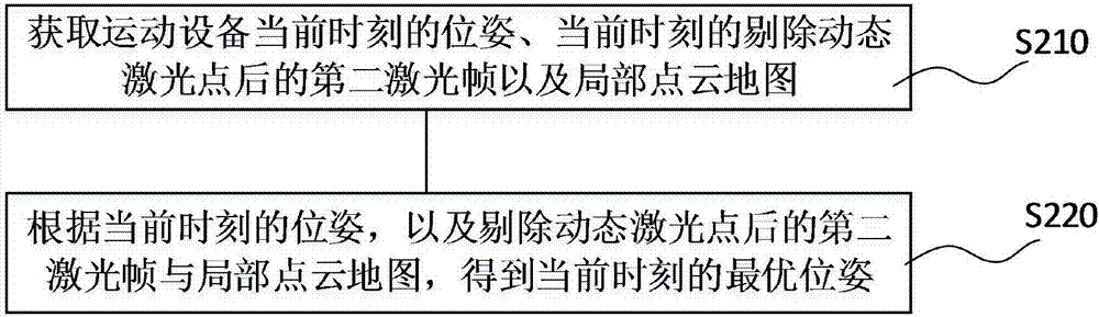
[0103] image 3 It is a schematic flow chart of Embodiment 2 of the odometer method of the present invention.

[0104] The odometer method of the present embodiment includes

[0105] Step S210: Obtain the current pose of the sports device, the current second laser frame after excluding laser dynamic points, and the local point cloud map.

[0106] A local probability grid map is introduced, and the probability value of the probability grid map is used as the basis for deleting dynamic points. Map the second laser frame to the local probability grid map. If the probability value of the grid where the laser point is located is less than the lowest probability value of the static grid, it is a dynamic grid, that is, the laser points in the grid are all dynamic laser points. Specifically, the following steps are included:

[0107] Step S211: Obtain the position coordinates of the laser point in the local probability grid map in the second laser frame according to the pose at the...

Embodiment 3

[0129] Figure 4 It is a schematic diagram of the module structure of the odometer device of the present invention.

[0130] An odometer device comprising

[0131] The first acquisition module acquires the pose of the sports equipment at the current moment;

[0132] The second acquisition module acquires the second laser frame at the current moment of the sports equipment;

[0133] The third acquisition module acquires the local point cloud map;

[0134] The first calculation module calculates the optimal pose at the current moment according to the pose at the current moment, as well as the second laser frame and the local point cloud map.

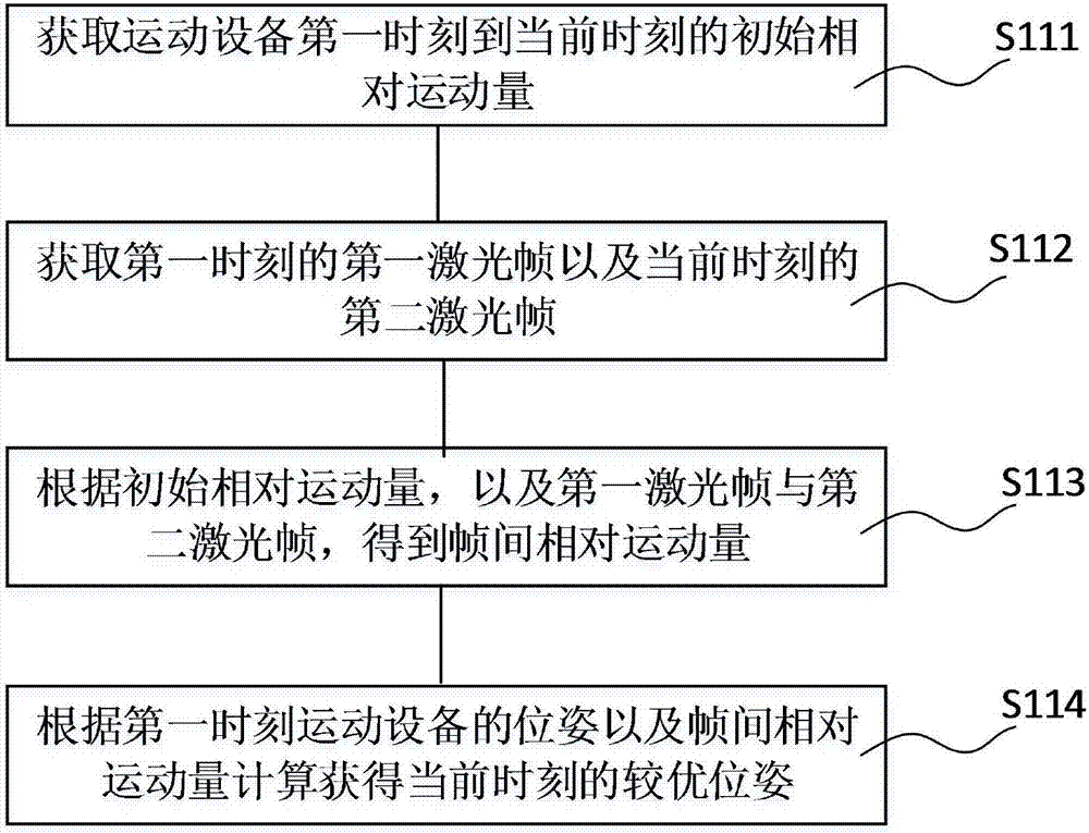
[0135] In this embodiment, as a further improvement, the first acquisition module is specifically configured to acquire a better pose at the current moment, specifically, the first acquisition module includes

[0136] The first acquisition unit acquires the initial relative exercise amount of the sports equipment from the first moment ...


PUM


Abstract

The invention discloses an odometer method and device for sports equipment; the odometer method comprises: acquiring current pose of sports equipment, current second laser frame and a local point cloud map; calculating according to the current pose, the second laser frame and the local point cloud map to obtain a current optimal pose; and other steps. In the odometer method, initial relative exercise amount and pose are acquired through the number of turns of a coded disc, laser inter-frame matching is performed by means of iterative nearest neighbor algorithm and the like, and accurate relative exercise amount and pose are acquired accordingly; the pose acquired in the above step is used as an initial value to perform matching on the laser frame and the local point cloud map so as to obtain more accurate pose and exercise amount that are then output. The odometer device provided herein enables the poor precision and accumulative error defects of an existing odometer to be overcome, and is applicable to general or special computing system environments or configurations.

Description

technical field [0001] The invention belongs to the technical field of sports equipment, in particular to an odometer method and an odometer device for the sports equipment. Background technique [0002] When a mobile robot moves in an indoor environment, the odometer information is the most basic information of the robot's motion state. A robot's odometry is a method that uses actuator movement data to estimate how much a robot's pose has changed over time. This pose change can be obtained by encoders and inertial navigation sensors. The traditional encoder estimating method only uses the accumulation of internal sensor information to obtain mileage information. For example, a robot is equipped with rotary encoders at its wheels or leg joints. When it moves forward for a period of time, it wants to know the approximate distance. Moving distance, with the help of a rotary encoder, the number of turns the wheel rotates can be measured, and if the circumference of the wheel ...

Claims


Application Information

Patent Timeline
Patent Type & Authority Applications(China)
IPC IPC(8): G01C22/00
Inventor 郭弟
Owner HANGZHOU JIAZHI TECH CO LTD
Why Eureka
Try Eureka