Grounding of a filter by means of an electrically conductive conductor trace on the filter element

A technology of filter elements and strip conductors, which can be used in membrane filters, filtration separation, electrical components, etc., and can solve expensive problems

Inactive Publication Date: 2014-04-30
ROBERT BOSCH GMBH
View PDF4 Cites 5 Cited by
  • Summary
  • Abstract
  • Description
  • Claims
  • Application Information

AI Technical Summary

Problems solved by technology

[0004] However, it is very expensive to construct the individual filter components to conduct electricity

Method used


Image

  • Grounding of a filter by means of an electrically conductive conductor trace on the filter element
  • Grounding of a filter by means of an electrically conductive conductor trace on the filter element
  • Grounding of a filter by means of an electrically conductive conductor trace on the filter element

Examples


Embodiment Construction

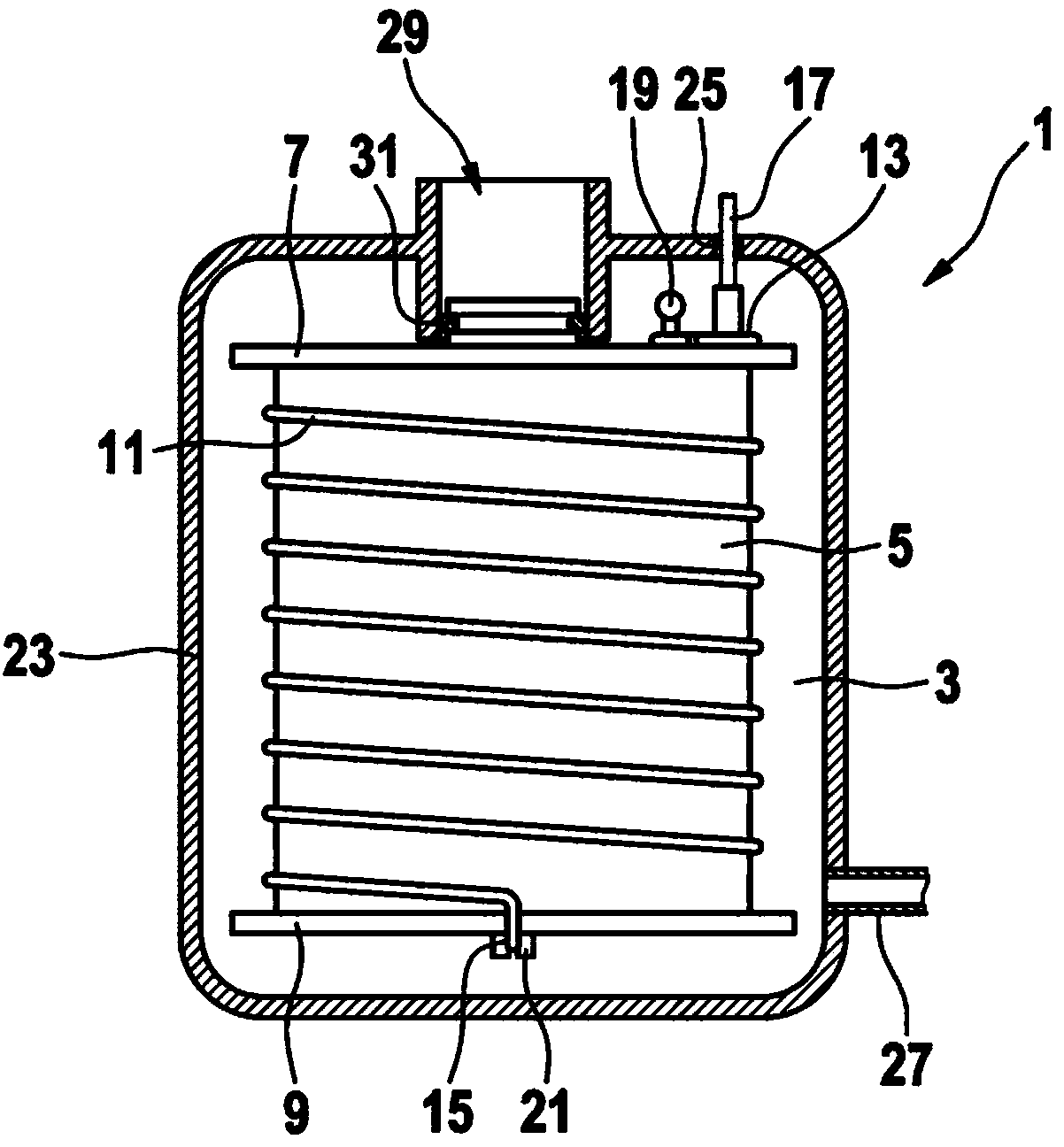
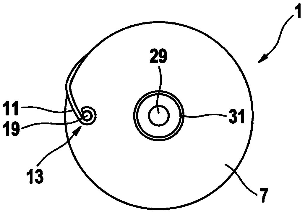
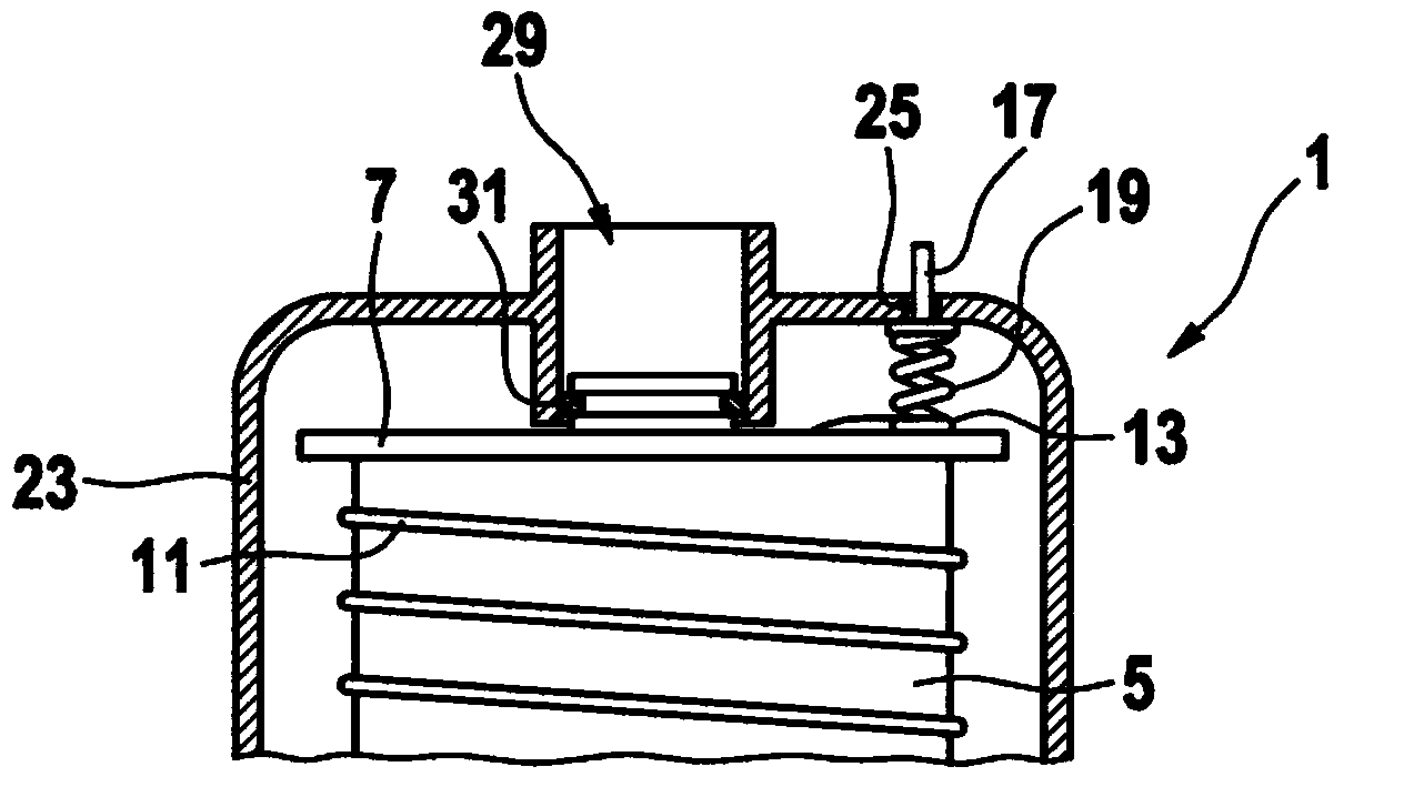
[0033] exist figure 1 A cross-section of a filter 1 , in particular a fuel filter, is shown in . The filter has a filter element 5 which is designed to remove unwanted particles from a liquid 3 , in particular fuel. The filter element 5 can here be, for example, a pleated filter paper, optionally with an internal support structure. The filter element 5 is arranged between the first end cap 7 and the second end cap 9 . The end caps 7 , 9 seal the filter element 5 in a fluid-tight manner against the liquid 3 in the interspace between the housing 23 and the filter element 5 . The liquid 3 thus has to pass through the filter element 5 before it can reach the cavity in the filter element 5 and be led there from there via the outlet 29 , possibly via a line. In the case of a fuel filter, the fuel is guided via the outlet 29 to the injection system of the internal combustion engine. The fuel filter can here be arranged, for example, in a fuel tank, in particular in a reservoir of...


PUM


Abstract

The invention relates to a filter (1) for filtering a liquid (3). The filter (1) comprises a filter element (5) that is designed to clean the liquid (3) of undesired particles. The filter element (5) is arranged between a first end cap (7) and a second end cap (9). The filter element (5), the first end cap (7) and the second end cap (9) are designed to be electrically nonconductive. An electrically conductive conductor trace (11) is arranged on the filter element (5) in order to dissipate electric charge.

Description

Background technique [0001] If the liquid flows through tight gaps or components with small cross-sections, friction between the component and the liquid will result. This can lead, in particular at high flow rates of the liquid, to a charge separation and thus to an electrostatic charging of the flow-through components. [0002] Especially in environments with components that can possibly be ignited, for example in fuel tanks, it is important to avoid electrostatic discharges, also known as “elektro static discharges” (ESD). Furthermore, electrostatic discharges must be avoided in order to avoid undesired effects on surrounding electrical installations. Furthermore, electrostatic discharges should be prevented in order to avoid material abrasion, so-called “pinholes”, by repeated spark discharges at the same point. [0003] In the case of filters, in particular fuel filters, this is achieved, for example, in that the individual components of the filter, such as the filter h...

Claims


Application Information

Patent Timeline
Patent Type & Authority Applications(China)
IPC IPC(8): B01D35/14
CPCB01D35/14B01D2201/50H05F3/00Y10T29/49117
Inventor M·拜尔
Owner ROBERT BOSCH GMBH
Why Eureka
Try Eureka