Easy-to-use nail puller

A nail puller, a convenient technology, applied in the directions of hand tools, hand tools, manufacturing tools, etc. suitable for fasteners, can solve the problems of large rivet holes in the cabinet, easy damage to the nail puller, etc., and achieves protection. , easy to disassemble, easy to use effect

Active Publication Date: 2015-09-09
CHENGDU ZHIRONG ZHICHUANG INTPROP MANAGEMENT CO LTD
View PDF7 Cites 0 Cited by
  • Summary
  • Abstract
  • Description
  • Claims
  • Application Information

AI Technical Summary

Problems solved by technology

[0003] The invention provides an easy-to-use nail puller, which solves the problem that the nail puller is easy to damage the nail puller when it is pulled out, and at the same time, it is easy to make the rivet holes on the cabinet body larger

Method used


Image

  • Easy-to-use nail puller
  • Easy-to-use nail puller
  • Easy-to-use nail puller

Examples


Embodiment 1

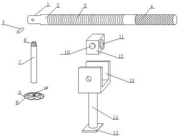
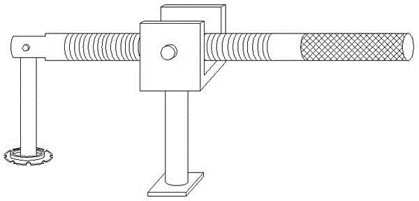
[0018] Such as Figure 1-Figure 3 The illustrated nail puller includes a U-shaped frame 13, a support bar 14 is connected to the lower end of the U-shaped frame 13, a backing plate 15 is connected to the lower end of the support bar 14, and a rotating block is arranged inside the U-shaped frame 13. 12. Both sides of the rotating block 12 are provided with a rotating shaft 10 connected to the U-shaped frame 13. The rotating block 12 can rotate in the U-shaped frame 13 with the rotating shaft 10 as the axis. The rotating block 12 is provided with a threaded passage Hole 11, the threaded through hole 11 is provided with a pressure rod 2, the middle part of the pressure rod 2 is provided with an external thread 3 cooperating with the threaded through hole 11, the left end of the pressure rod 2 is provided with a mounting groove 1, and the mounting groove 1 is positioned by The pin 5 is connected with a connecting rod 7, the upper end of the connecting rod 7 is provided with a conn...

Embodiment 2

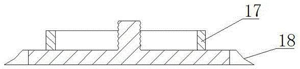
[0022] In this embodiment, the following structure is added on the basis of Embodiment 1: an annular weak magnet 17 is bonded to the upper end surface of the nail pulling disc 9 .

[0023] In this embodiment, the ring-shaped weak magnet 17 is bonded to the upper end surface of the nail pulling disc 9, which not only can absorb the rivet taken out, but also prevent it from falling into the gap or narrow place inside the cabinet, which is inconvenient to find and cannot be reused. Due to excessive force when pulling out the nail, the rivet will directly shoot out, which can easily cause damage to the workers around. Therefore, in order to protect the worker and facilitate the collection of the rivet, a weak magnet 17 is added on the nail pulling plate 9.

Embodiment 3

[0025] This embodiment is optimized as follows on the basis of embodiment 1 or embodiment 2: the thickness of the nail-pulling disk 9 is 1-2.5 millimeters, and the upper end surface of the nail-pulling disk 9 is smaller than the lower end surface of the nail-pulling disk 9 , and the circumferential surface of the nail pulling disc 9 is an arcuate surface 18.

[0026] In this embodiment, in order to quickly cut into the bonding surface between the rivet and the cabinet body for the nail pulling disc 9, its thickness is generally not greater than 2.5 mm. The circumferential surface of 9 is set to arc surface 18, facilitates pulling out nail dish 9 and cuts in.


PUM

PropertyMeasurementUnit
thicknessaaaaaaaaaa
angleaaaaaaaaaa

Abstract

The invention provides a nail puller convenient to use. The nail puller is characterized in that the lower end of a U-shaped frame is connected with a supporting rod, the lower end of the supporting rod is connected with a base plate, a rotating block is arranged inside the U-shaped frame, rotating shafts connected with the U-shaped frame are arranged on the two sides of the rotating block, and the rotating block can rotate in the U-shaped frame with the rotating shafts as axes; a threaded through hole is formed in the rotating block, a compression bar is arranged in the threaded through hole, and external threads matched with the threaded through hole are arranged in the middle of the compression bar; a mounting groove is formed in the left side end of the compression bar and connected with a connecting bar through a locating pin, a connecting plate which is embedded into the mounting groove is arranged at the upper end of the connecting bar, and a pin hole is formed in the connecting plate; a nail pulling plate is connected with the lower end of the connecting bar, a threaded column is arranged on the upper end face of the nail pulling plate and in threaded connection with the lower end of the connecting bar, and a plurality of nail pulling arc-shaped notches which are all different in size are formed in the circumferential surface of the nail pulling plate. The nail puller is convenient to demount, the torque of the compression bar can be adjusted, nails can be pulled with little effort, the nail pulling plate can rotate around the locating pin, and it is guaranteed that rivets can be pulled out along rivet holes.

Description

technical field [0001] The invention relates to a nail puller, in particular to a nail puller which is easy to use. Background technique [0002] In order to set up some mounting plates for installing and supporting electrical components inside the power cabinet, it is often necessary to drive some rivets into the cabinet. When installing the mounting plate, sometimes the mounting plate cannot be installed due to the deviation in the size of the fixing parts. , At this time, it is necessary to pull out the rivets that have been driven into the cabinet in advance and fix them again. In the past, the pressure required for different types of rivets was different when using the previous rivets, which made it necessary for the staff to pull out some large rivets. Not only is it laborious and time-consuming, but it is also very easy to damage the nail puller; at the same time, because the rivets will be pulled out in a straight line when the previous nail puller is pulled out, com...

Claims


Application Information

Patent Timeline
Patent Type & Authority Patents(China)
IPC IPC(8): B21J15/50B25B31/00
Inventor 李胜峰
Owner CHENGDU ZHIRONG ZHICHUANG INTPROP MANAGEMENT CO LTD
Why Eureka
Try Eureka