rotatable brick clamp

A technology of brick clamp and front clamp, which is applied in the direction of vehicles with cranes, load suspension components, transportation and packaging, etc., can solve the problems of incomplete loading and unloading, difficult loading and unloading, etc., achieve all-round loading and unloading, smooth loading and unloading, and solve loading and unloading difficulties Effect

Inactive Publication Date: 2015-09-16
万红章
View PDF12 Cites 0 Cited by
  • Summary
  • Abstract
  • Description
  • Claims
  • Application Information

AI Technical Summary

Problems solved by technology

However, when the loading and unloading site is small, it is difficult to load and unload, or even impossible to complete the loading and unloading

Method used


Image

  • rotatable brick clamp
  • rotatable brick clamp

Examples


Embodiment Construction

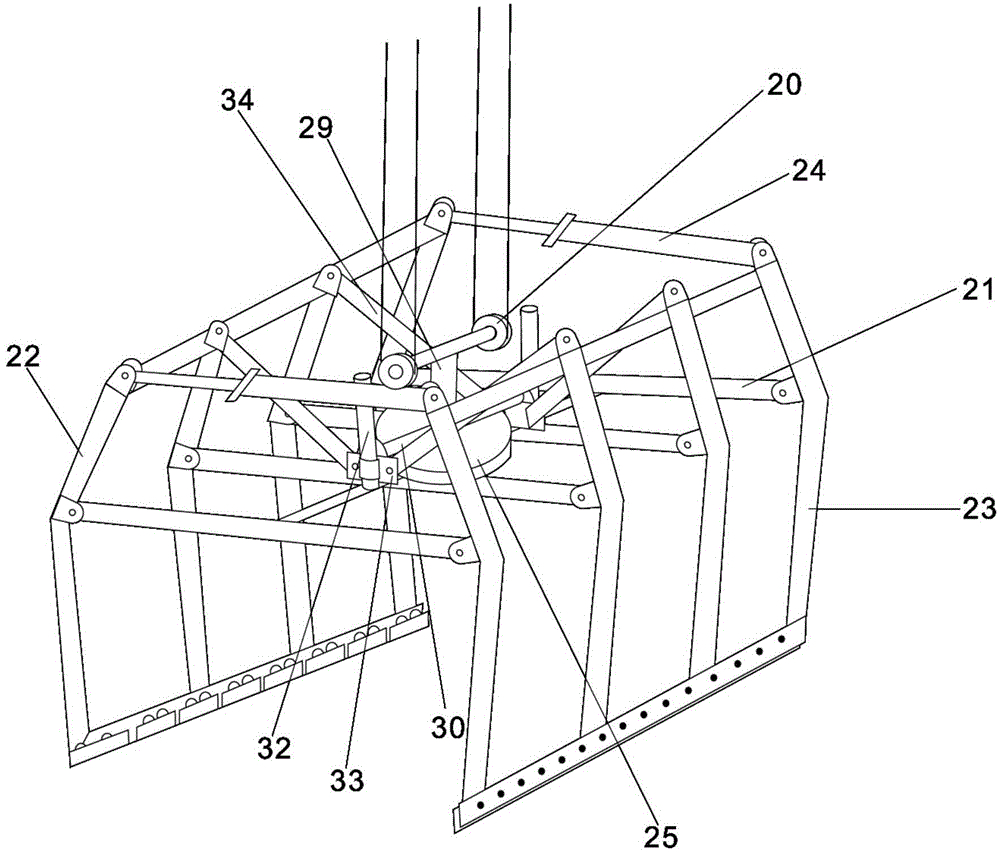
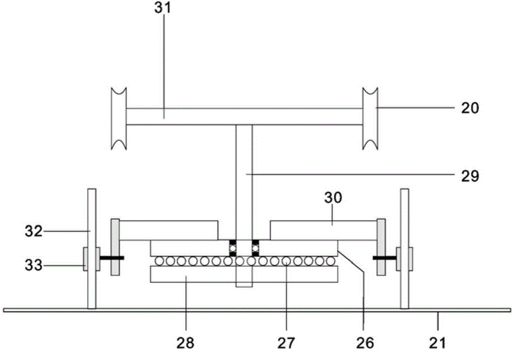
[0010] Attached below figure 1 , 2 An embodiment of the present invention is described.

[0011] A rotatable brick clamp is composed of a horizontal bracket 21, a front clamp arm 22, a rear clamp arm 23 and a clamping oil cylinder 24; Both sides, and the clamping oil cylinder 24 is hinged between the front clamping arm 22 and the rear clamping arm 23 upper ends; the top of the horizontal support 21 is provided with a rotating device 25, and the rotating device 25 consists of an upper turntable 26, a pressure bearing 27 and The lower turntable 28 is composed of a vertical shaft 29 fixed on the lower turntable 28, the upper turntable 26 is mounted on the vertical shaft 29 through a bearing, a horizontal connecting rod 30 is fixed on the upper turntable 26, a horizontal shaft 31 is fixed on the upper end of the vertical shaft 29, and the two movable pulleys 20 are respectively Installed on the two ends of the horizontal shaft 31, the two ends of the horizontal connecting rod 30...


PUM


Abstract

The invention discloses a rotary brick clamp. The rotary brick clamp comprises a horizontal support, a front clamping arm, a back clamping arm and a clamping cylinder, wherein the middle of the front clamping arm and the middle of the back clamping arm are symmetrically hinged on the front side and the back side of the horizontal support; the clamping cylinder is hinged between the upper end of the front clamping arm and the upper end of the back clamping arm; a rotation device is arranged above the horizontal support; the rotation device comprises an upper rotation plate, a pressure bearing and a lower rotation plate; a vertical shaft is fixed on the lower rotation plate; the upper rotation plate is mounted on the vertical shaft through the bearing; a horizontal connection rod is fixed on the upper rotation plate; a horizontal shaft is fixed on the upper end of the vertical shaft; two movable pulleys are mounted on two ends of the horizontal shaft respectively; movable supports are fixed on two ends of the horizontal connection rod; a short stand column is fixed on the horizontal support; the movable supports are sleeved on the short stand column; one end of a connection plate is hinged with the upper end of the front clamping arm and the upper end of the back clamping arm; and the other end of the connection plate is symmetrically hinged on two sides of the movable supports. According to the rotary brick clamp, the assembly and disassembly difficulties caused due to inconsistence between directions of brick stacks and the clamping direction of the brick clamp and narrow assembly and disassembly places can be solved.

Description

technical field [0001] The invention relates to the technical field of automatic loading and unloading, in particular to a rotatable brick clamp. Background technique [0002] The closest existing technology to the present invention is the invention patent "Automatic Loading and Unloading Brick Truck (CN103303181A)" applied by the applicant. The brick clamp used in this vehicle cannot be rotated. It is difficult to complete the loading and unloading of brick stomps. Especially when loading, it is necessary to adjust the position of the brick transporter first, so that the longitudinal direction of the carriage of the brick transporter is consistent with the orientation of the bricks, and the rear end of the carriage is facing the bricks, so as to ensure that the clamping direction of the brick clamps is consistent with the direction of the bricks. The orientation is consistent, so that the loading of bricks can be successfully completed. However, when the loading and unloa...

Claims


Application Information

Patent Timeline
Patent Type & Authority Patents(China)
IPC IPC(8): B66C1/42B60P1/54
Inventor 万红章
Owner 万红章
Why Eureka
Try Eureka