Clamp

A technology for clips and clamping parts, applied in printing, binding and other directions, can solve the problem of too many parts, and achieve the effect of reducing the number, improving the convenience of use and improving the convenience.

Inactive Publication Date: 2008-04-23
KOKUYO CO LTD
View PDF2 Cites 4 Cited by
  • Summary
  • Abstract
  • Description
  • Claims
  • Application Information

AI Technical Summary

Problems solved by technology

Therefore, clips are required to hold the storage box, and in addition to clips, magnets are also required for displaying memos, so there is a disadvantage that many parts are attached to board-like objects.

Method used


Image

  • Clamp
  • Clamp
  • Clamp

Examples


Embodiment Construction

[0036] Hereinafter, embodiments of the present invention will be described with reference to the drawings.

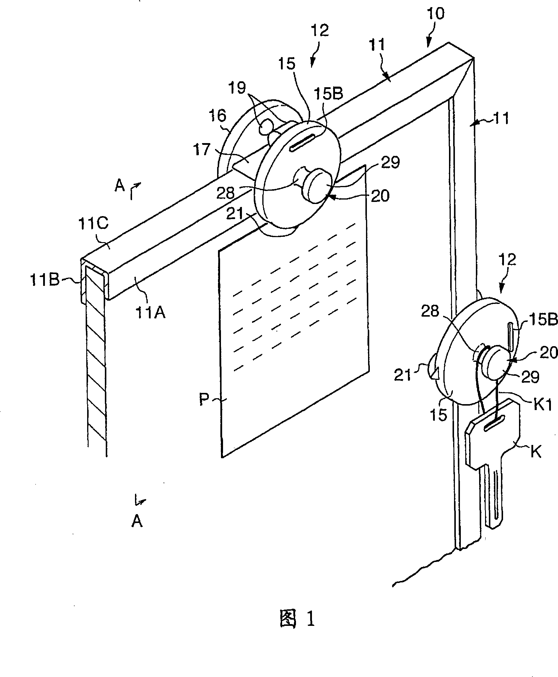
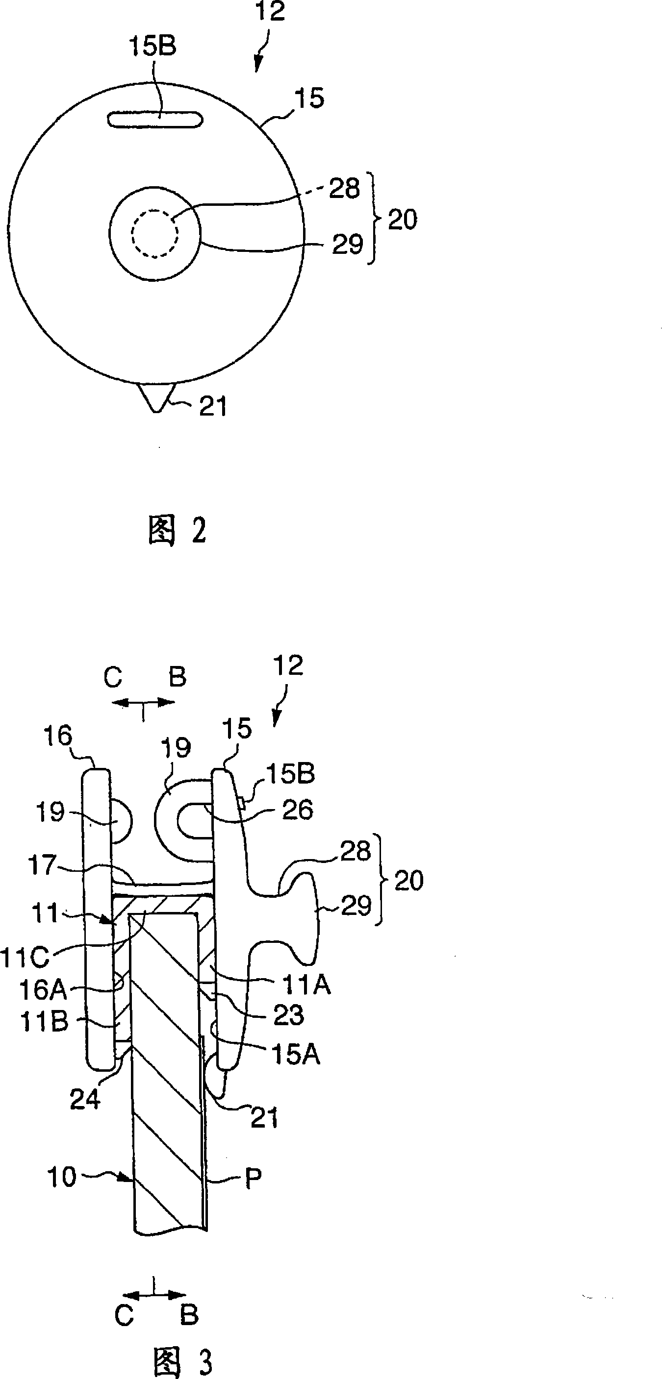
[0037] In FIG. 1 , a partial schematic perspective view of a board-like article to which a clip according to an embodiment is attached is shown. In addition, FIG. 2 shows a front view of the clip, and FIG. 3 shows a cross-sectional view along line A-A of FIG. 1 . In these figures, a board-like object 10 is formed into a square shape as viewed from the front, and its surface is processed so that it can be used as a writing surface or a notice surface. In addition, the plate-like article 10 is provided with edge members 11 at the ends along the four sides, and clips 12 are detachably attached to the edge members 11 .

[0038] The edge part 11 is set in a cross-sectional shape similar to a U, including: a front part 11A located on the front side of the board object 10, a back part 11B located on the back side of the board object 10, and connecting these front parts 11A A...


PUM


Abstract

The invention provides a clip which can hold papers at the surface side of a plate type object and also can hold stated small objects in a manner of hook-hanging or suspension-hanging. The clip (12) is arranged on an edge component (11) which is arranged along the end of the plate type object (10). The clip (12) comprises a first holding component (15) and a second holding component (16) positioned at the front side and the back side of the plate type object (10) and hook-hung on the edge component (11); a connection element (17) which is connected with the opposite sides (15A and 16A) of the first holding component (15) and the second holding component (16); noses (19 and 19) which are respectively arranged on the opposite sides (15A and 16A) and are contacted with each other; a hook part (20) which is heaved from the surface of the first holding component (15); and a pressing part (21) which is arranged on the first holding component (15) and which can press papers (P) on the plate type object (10).

Description

technical field [0001] The present invention relates to a clip, and more particularly, to a clip capable of being attached to an edge member on the periphery of a plate-like object. Background technique [0002] Conventionally, there are known clips that are detachably provided on edge members located on the outer periphery of boards such as whiteboards (for example, refer to Patent Documents 1 and 2). In Patent Document 1, a tablet is sandwiched between a pair of front and back sheets, and the sheets are hooked to a frame around the tablet. In addition, in this document, the storage box can be hung by hooks located between the respective sheet bodies. [0003] Patent Document 1: Japanese Publication No. 46-4975 [0004] Patent Document 2: Japanese Publication No. 42-12371 [0005] However, magnets, thumbtacks, etc. are used to hold the memo or the like on the front surface of the writing surface or notice surface of the above-mentioned board-like objects. Therefore, cli...

Claims


Application Information

Patent Timeline
Patent Type & Authority Applications(China)
IPC IPC(8): B42F1/02
Inventor 增山正明加藤达也
Owner KOKUYO CO LTD
Why Eureka
Try Eureka