Hinge structure

A technology of hinge structure and cylinder, which is applied in gas shock absorber, pivot connection and other directions, can solve the problems of performance loss of hinge structure, damage of electronic device, and heavy weight of the two pivoted parts, so as to avoid performance loss. Effect

Inactive Publication Date: 2014-05-07
HONG FU JIN PRECISION IND (SHENZHEN) CO LTD +1
View PDF0 Cites 6 Cited by
  • Summary
  • Abstract
  • Description
  • Claims
  • Application Information

AI Technical Summary

Problems solved by technology

However, in the current hinge structure, if the opening or closing force is too large, the two pivoted parts are easily damaged by the impact of excessive force, and the performance of the hinge structure is also easily damaged.
In addition, in some electronic devices (such as flatbed scanners), the weight of the two pivoted parts is very heavy, and it is easy to cause damage to the electronic device due to its large inertia when it is opened or closed.

Method used


Image

  • Hinge structure
  • Hinge structure
  • Hinge structure

Examples


Embodiment Construction

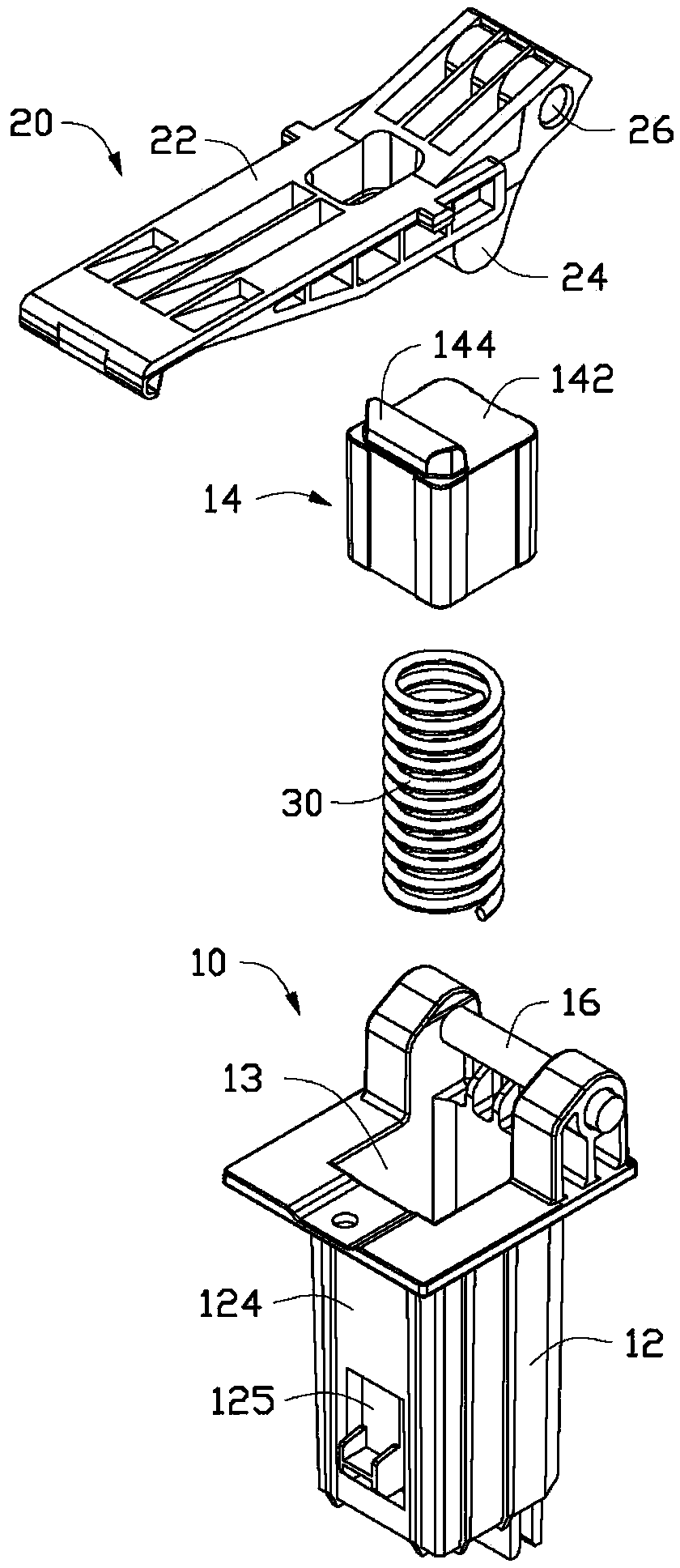
[0024] See Figure 1 to Figure 3 In a preferred embodiment of the present invention, a hinge structure includes a base 10, a rotating member 20, and an elastic member 30.

[0025] The base 10 includes a cylinder 12 and a piston 14 matched with the cylinder 12, and the base 10 also includes a pivot shaft 16.

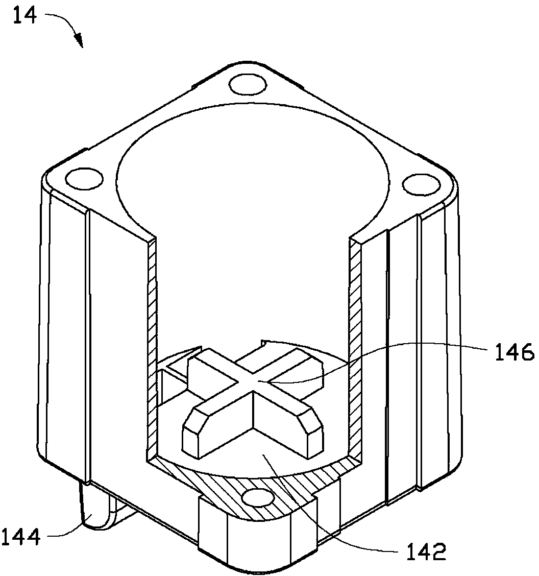
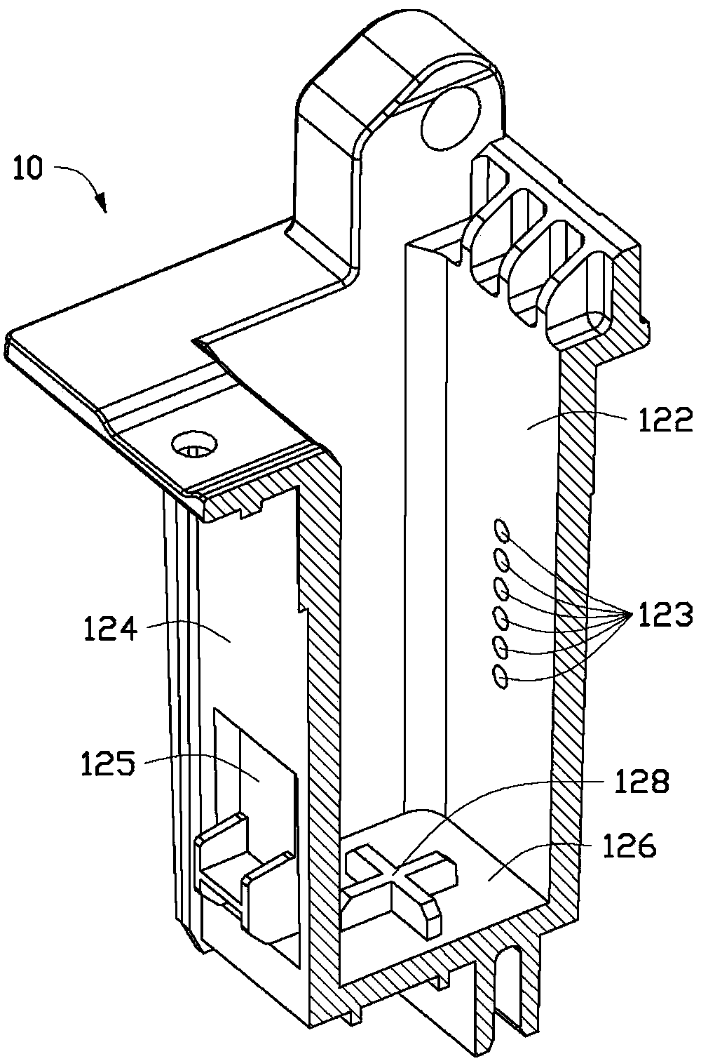
[0026] The cross-section of the cylinder 12 is approximately a rectangle, and the cross-section of the piston 14 matched with it is also approximately a rectangle. Such as Figure 5 with Image 6 As shown, an air chamber 13 is formed between the cylinder 12 and the piston 14. When the piston 14 moves along the axial direction of the cylinder 12 (the vertical direction shown in the figure), the piston 14 will A force (squeezing or stretching) is generated on the gas in the gas chamber 13. Those skilled in the art should understand that, in other embodiments, the cross-section of the cylinder 12 may also have other shapes, such as a circle, a hexagon, etc., and the shape of th...


PUM


Abstract

The invention discloses a hinge structure which comprises a base, a rotating piece connected with the base in a pivoting manner, and an elastic piece arranged in an air cylinder, wherein the base comprises the air cylinder and a piston which is arranged in the air cylinder and matched with the air cylinder; the air cylinder is provided with a plurality of cushion air holes; the two ends of the elastic piece are connected with a bottom wall of the air cylinder and the piston in a push-against manner respectively; and when the rotating piece pivots relative to the base, the piston is driven by the rotating piece and the elastic piece to make axial motion along the air cylinder.

Description

Technical field [0001] The invention relates to a hinge structure, in particular to a hinge structure used in an electronic device. Background technique [0002] A hinge structure is often provided in electronic devices such as notebook computers, game consoles, e-books, and mobile phones to realize that the two pivoted parts (such as the display and the main body) can be relatively rotated (such as opened or closed). However, in the current hinge structure, if the force of opening or closing is too large, the two pivotally connected parts are easily damaged due to excessive force impact, and the performance of the hinge structure is also easily damaged. In addition, in some electronic devices (such as flatbed scanners), the two pivotally connected parts weigh a lot, and their greater inertia can easily damage the electronic device when opened or closed. Summary of the invention [0003] In view of the above, it is necessary to provide a hinge structure used in an electronic devi...

Claims


Application Information

Patent Timeline
Patent Type & Authority Applications(China)
IPC IPC(8): F16C11/12F16F9/02
Inventor 郑丰昆詹志中
Owner HONG FU JIN PRECISION IND (SHENZHEN) CO LTD
Why Eureka
Try Eureka