Energy-saving stove

A stove and stove ring technology, which is applied to household stoves/stoves, stove/stove tops, and household stoves, etc., can solve the problems of low efficiency and large heat loss of stoves, and achieve the effect of high thermal efficiency and less heat loss.

Inactive Publication Date: 2009-11-18
ZHEJIANG UNIV OF TECH
View PDF1 Cites 11 Cited by
  • Summary
  • Abstract
  • Description
  • Claims
  • Application Information

AI Technical Summary

Problems solved by technology

[0007] In order to solve the shortcomings of large heat loss and low efficiency of existing stoves, a stove with small heat loss, high thermal efficiency and simple structure is provided

Method used


Image

  • Energy-saving stove
  • Energy-saving stove
  • Energy-saving stove

Examples


Embodiment 1

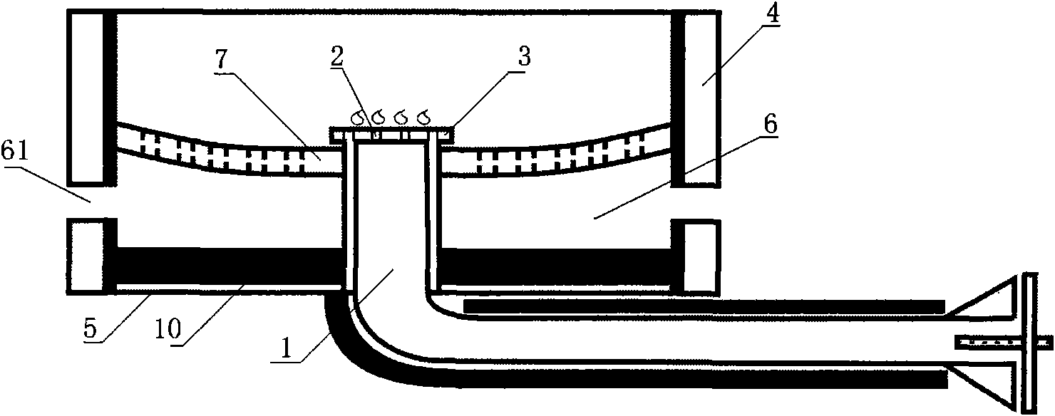
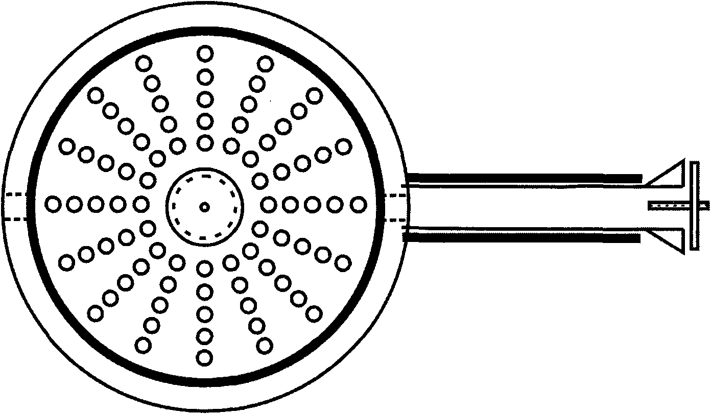
[0040] refer to figure 1 , Picture 1-1

[0041] The energy-saving stove includes a mixing chamber for combustible gas and air. The mixing chamber 1 communicates with the nozzle hole 2 on the combustion head. The combustion head 3 is set in the furnace 6 surrounded by the furnace ring 4 and the furnace bottom 5. The furnace ring 4 has a shape that can cooperate with the pot body and the furnace bottom 5 to form a closed furnace 6. The closed furnace 6 has a flue gas outlet 61, and the combustion head 3 and the flue gas lead A flue gas flow path is formed between the outlets; a porous heat storage radiation plate 7 is blocked on the flue gas flow path.

[0042] The position of the smoke outlet 61 is lower than the combustion head 3 , and the heat storage radiation plate 7 is higher than the smoke outlet 3 and lower than the combustion head 3 .

[0043] The furnace ring 4 and the furnace bottom 5 are lined with a heat insulating material layer. The said fuel of the present i...

Embodiment 2

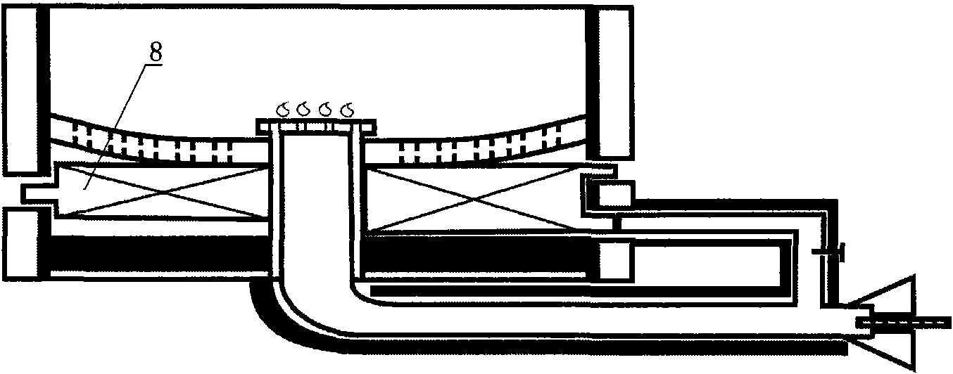
[0045] refer to figure 2 , diagram 2-1

[0046] The difference between this embodiment and the first embodiment is that the exhaust gas drawn out through the flue gas outlet 61 exchanges heat with the air that will enter the mixing chamber 1 through the heat exchanger 8 .

[0047] The heat exchanger 8 is arranged in the furnace 6 .

Embodiment 3

[0049] refer to image 3 , Figure 3-1

[0050] The difference between this embodiment and the second embodiment lies in that: the heat exchanger 8 is arranged in the furnace hoop 4 .


PUM


Abstract

The invention provides an energy-saving stove. The stove comprises a mixing chamber of fuel and air, the mixing chamber is communicated with a jet hole on a combustion head; the combustion head is arranged in a furnace tank circled by a stove ring and a stove bottom; the closed furnace is provided with a smoke gas outlet; a smoke gas flow passage is formed between the combustion head and the smoke gas outlet; the smoke gas flow passage is provided with porous thermal storage radiant panels for stopping. The energy-saving stove has the advantages of small heat loss and high heat efficiency.

Description

technical field [0001] The invention relates to an energy-saving stove. Background technique [0002] The combustion methods of gas stoves or oil stoves currently on the market are generally open combustion, that is, the stove plate is exposed, and the flame is in direct contact with the surrounding air during combustion, without any enclosure structure and heat recovery device. The flames of ordinary gas stoves are scattered and weak, and have almost no force on the bottom of the pot. Heat, resulting in very serious heat loss; due to its design flaws, the fuel inside the combustion zone cannot be in good contact with the air, resulting in incomplete combustion of the fuel. Therefore, ordinary stoves are inefficient to use and cause serious energy waste. [0003] The most prominent shortcoming of this combustion mode is that heat loss is big, traces it to its cause: the one, owing to be open combustion, the radiation of flame has only a part to be absorbed by the bottom of...

Claims


Application Information

Patent Timeline
Patent Type & Authority Applications(China)
IPC IPC(8): F24C3/04F24C5/00F24C15/10F24C15/24F24C15/34F23L15/00
CPCY02B40/166Y02B40/00Y02E20/34
Inventor 傅晓云
Owner ZHEJIANG UNIV OF TECH
Why Eureka
Try Eureka