
Device and method for detecting wiring of stator lead-out wires of three-phase permanent magnet motor

A technology for lead-out wires and stators, applied in the field of stator lead-out wire wiring detection devices, can solve problems such as technical inability to detect, loss, and complete scrapping of three-phase permanent magnet motors, and achieve timely correction, convenient operation, and avoidance of charging The effect of magnetic errors

Active Publication Date: 2018-03-23
GUANGDONG MEIZHI PRECISION MFG
View PDF5 Cites 0 Cited by
  • Summary
  • Abstract
  • Description
  • Claims
  • Application Information

AI Technical Summary

Problems solved by technology

[0004] The disadvantage of the above-mentioned inspection method is that the relevant technology can only detect whether the steering of the motor is wrong, so as to correct the wiring mode that causes the wrong steering in time. , B-phase coil and C-phase coil are incorrectly connected in sequence, because the three-phase permanent magnet motor is running forward, the relevant technology cannot detect it, and it can only be found in the subsequent magnetization process, which will lead to the three-phase permanent magnet motor. machine scrapped, causing huge losses

Method used


Image

  • Device and method for detecting wiring of stator lead-out wires of three-phase permanent magnet motor
  • Device and method for detecting wiring of stator lead-out wires of three-phase permanent magnet motor
  • Device and method for detecting wiring of stator lead-out wires of three-phase permanent magnet motor

Examples


Embodiment Construction

[0043] Embodiments of the present invention are described in detail below, examples of which are shown in the drawings, wherein the same or similar reference numerals designate the same or similar elements or elements having the same or similar functions throughout. The embodiments described below by referring to the figures are exemplary only for explaining the present invention and should not be construed as limiting the present invention.

[0044] The following disclosure provides many different embodiments or examples for implementing different structures of the present invention. To simplify the disclosure of the present invention, components and arrangements of specific examples are described below. Of course, they are only examples and are not intended to limit the invention. Furthermore, the present invention may repeat reference numerals and / or letters in different instances. This repetition is for the purpose of simplicity and clarity and does not in itself indicat...


PUM


Abstract

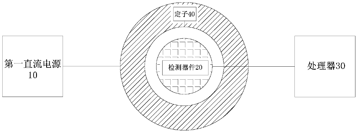
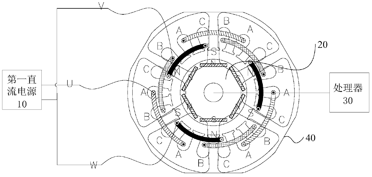
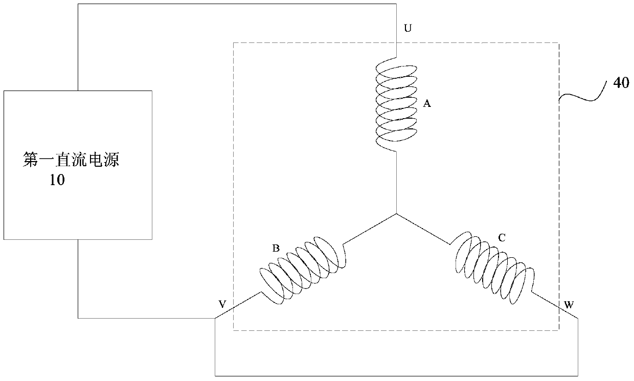
The invention discloses a device and method for detecting the wiring of stator lead-out wires of a three-phase permanent magnet motor, wherein the device for detecting the wiring of stator lead-out wires of a three-phase permanent magnet motor comprises: a first DC power supply, a first DC power supply The first end of the first DC power supply is connected to any one phase lead-out line of the stator, and the second end of the first DC power supply is connected to the other two parallel-connected lead-out lines of the stator; the detection device is used to detect that the three-phase coil of the stator is energized to form a The magnetic field of the stator, and generate a detection signal; the processor, the processor is connected with the detection device, and the processor is used to judge whether the wiring of the three-phase lead wire of the stator is correct according to the preset threshold and the detection signal. The stator lead wire wiring detection device and method of the three-phase permanent magnet motor of the present invention can quickly identify the stator lead wire wiring error, thereby avoiding the resulting magnetization error, facilitating timely correction, and requiring no experience for operators , which is easy to implement.

Description

technical field [0001] The invention relates to the technical field of motors, in particular to a detection device and method for wiring of stator lead-out wires of a three-phase permanent magnet motor. Background technique [0002] For a three-phase permanent magnet motor, when it is necessary to magnetize the rotor through the stator coil, a positive current of 2I is usually passed into the A-phase coil of the stator, and a negative current of 1 is passed into the B and C two-phase coils at the same time. To the current, thus forming a magnetizing magnetic field. The number of poles of the magnetizing magnetic field is equal to the number of poles of the rotor, and the magnetic poles of the magnetizing magnetic field are facing the permanent magnets to be magnetized in the rotor. It should be noted that when the three-phase permanent magnet motor needs to magnetize the rotor through the stator coil, the A, B, and C three-phase coils of the stator need to be connected with...

Claims


Application Information

Patent Timeline
Patent Type & Authority Patents(China)
IPC IPC(8): G01R31/02
Inventor 刘文扬杨泾涛
Owner GUANGDONG MEIZHI PRECISION MFG
Learn More