
Magnetic field sensor

A magnetic field sensor, sensor body technology, applied in the direction of the size/direction of the magnetic field, can solve the problems of limited linear response frequency range, reduced signal-to-noise ratio, and lifting the weight of the structural part, reducing the area of ​​a single turn and amplifying the strength of the magnetic field , the effect of improving sensitivity

Active Publication Date: 2016-03-23
INST OF ELECTRONICS CHINESE ACAD OF SCI
View PDF5 Cites 0 Cited by
  • Summary
  • Abstract
  • Description
  • Claims
  • Application Information

AI Technical Summary

Problems solved by technology

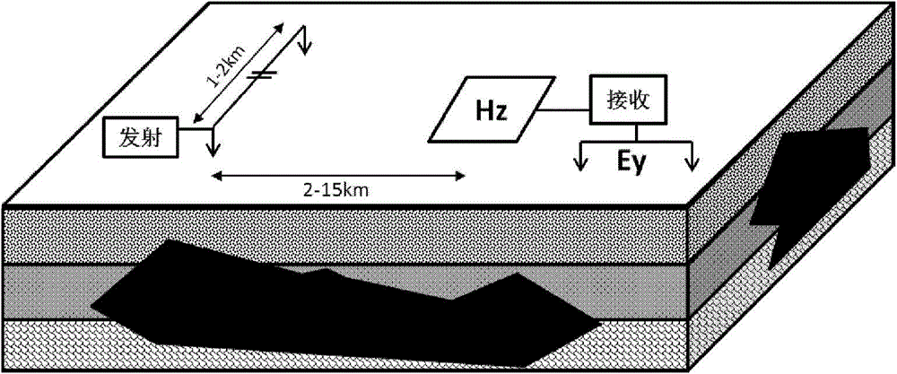
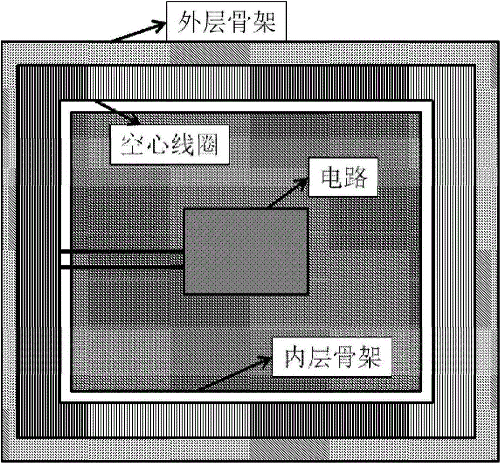
[0008] (1) The sensitivity of the magnetic field sensor is not enough. The total area of ​​the air-core coil inside the sensor is about 100m2. In the application of TFEM and LOTEM, the area of ​​the air-core coil needs to reach more than 1000m2, which requires an increase in the number of turns of the air-core coil and the area of ​​​​a single turn. The weight of the hollow coil will increase the weight of the structural part at the same time, the volume and weight of the sensor will become larger, and it will be very difficult to carry it in the field. For example, a certain magnetic field sensor has a size of 6.25m×6.25m and a weight of 25kg;
[0009] (2) The frequency linear response range of the magnetic field sensor is insufficient
Due to the existence of resonance frequency, the bandwidth is difficult to meet the requirements, and the traditional critical damping matching technology has a limited linear response frequency range, which does not give full play to the performance of the magnetic field sensor;
[0010] (3) The sensitivity of the magnetic field sensor is fixed and cannot be adjusted according to the actual situation
In order to achieve the purpose of detecting underground targets at different depths during construction of LOTEM and TFEM, the offset distance of transmission and reception often changes greatly, and the corresponding received signal strength also changes greatly. The receiving sensitivity of existing magnetic field sensors adopts a fixed form. When the offset distance increases, the amplitude of the received signal weakens rapidly, and the signal-to-noise ratio decreases, which cannot meet the requirements of effective acquisition of the receiver signal.

Method used


Image

  • Magnetic field sensor
  • Magnetic field sensor
  • Magnetic field sensor

Examples


Embodiment Construction

[0031] In order to make the object, technical solution and advantages of the present invention clearer, the present invention will be described in further detail below in conjunction with specific embodiments and with reference to the accompanying drawings. It should be noted that, in the drawings or descriptions of the specification, similar or identical parts all use the same figure numbers. Implementations not shown or described in the accompanying drawings are forms known to those of ordinary skill in the art. Additionally, while illustrations of parameters including particular values ​​may be provided herein, it should be understood that the parameters need not be exactly equal to the corresponding values, but rather may approximate the corresponding values ​​within acceptable error margins or design constraints. The directional terms mentioned in the embodiments, such as "upper", "lower", "front", "rear", "left", "right", etc., are only referring to the directions of the...


PUM


Abstract

The invention provides a magnetic field sensor. The magnetic field sensor comprises a sensor body, wherein a signal amplifying module, a single-ended turn difference module and a power supply and control module are included in the sensor body. The sensor body is used for detecting a magnetic field signal of the environment where the sensor body is located and comprises a magnetic core which is wrapped by an inner cylinder and an induction coil which is wound on the periphery of the inner cylinder, and a middle tap of the induction coil is connected with the ground. The signal amplifying module is connected with the two ends of the induction coil, is used for amplifying the magnetic field signal detected by the sensor body, and outputs the signal through a single-ended mode, the single-ended turn difference module is connected with the signal amplifying module and used for converting the magnetic field signal output by the signal amplifying module in the single-ended mode into the difference type signal, and the power supply and control module is used for supplying power sources to the signal amplifying module and the single-ended turn difference module and outputs the difference type detected signal output by the single-ended turn difference module. According to the magnetic field sensor, a hollow coil is replaced by a structure with a magnetic core coil, and under the situation that the number of turns is not changed, compared with the hollow coil which improves the sensitivity of the sensor by increasing the area of a single turn, the sensitivity of the sensor is improved by selecting the suitable magnetic core coil.

Description

technical field [0001] The invention relates to the technical field of magnetic field sensors, in particular to a magnetic field sensor. Background technique [0002] With the increasing demand for oil and gas due to economic development, conventional oil and gas resources can no longer meet the growth of this demand, and most of my country's oil depends on imports, and the growth rate of crude oil production is not as good as the growth of domestic oil demand. Facing such a severe oil resource environment, unconventional oil and gas shale gas has attracted great attention. my country is rich in shale gas resources and has great exploration potential. However, the geological conditions of shale gas are complex and special, and the accumulation conditions of unconventional oil and gas reservoirs are complex, with tight reservoirs and strong heterogeneity. The exploration and development of shale gas resources in my country is still in its infancy, there is no systematic sup...

Claims


Application Information

Patent Timeline
Patent Type & Authority Patents(China)
IPC IPC(8): G01R33/02
Inventor 朱万华刘凯闫彬刘雷松方广有
Owner INST OF ELECTRONICS CHINESE ACAD OF SCI
Learn More