
A rotating friction generator with constant current output

A technology of rotating friction and constant current, applied in the direction of friction generators, etc., can solve the problems of high cost, difficult output current, low power generation efficiency, etc., achieve good social and economic benefits, convenient realization, and simple structure

Active Publication Date: 2016-08-17
BEIJING INST OF NANOENERGY & NANOSYST
View PDF10 Cites 0 Cited by
  • Summary
  • Abstract
  • Description
  • Claims
  • Application Information

AI Technical Summary

Problems solved by technology

However, the design of micro electrostatic generators is mainly based on inorganic silicon materials, and the manufacture of devices requires complex processes and precise operations.
The preparation of the whole device requires large-scale equipment and special production conditions, and the cost is too high, which is not conducive to the commercialization and daily application of generators
Chinese invention patent applications with application numbers 201210149940.8 and 201210160542.6 disclose a friction generator, which generates electricity through frictional electricity generation and charge separation, but the friction generator can only generate pulsed current output
The Chinese invention patent application with the application number 200910080638.X discloses a rotary friction generator, which generates electric charge through the rotary friction between the friction material on the stator and the rotor, but it is difficult for the rotary friction generator to output to the external circuit current, the power generation efficiency is very low

Method used


Image

  • A rotating friction generator with constant current output
  • A rotating friction generator with constant current output
  • A rotating friction generator with constant current output

Examples


Embodiment Construction

[0046] In order to make the object, technical solution and advantages of the present invention clearer, the present invention will be further described in detail below in conjunction with specific embodiments and with reference to the accompanying drawings.

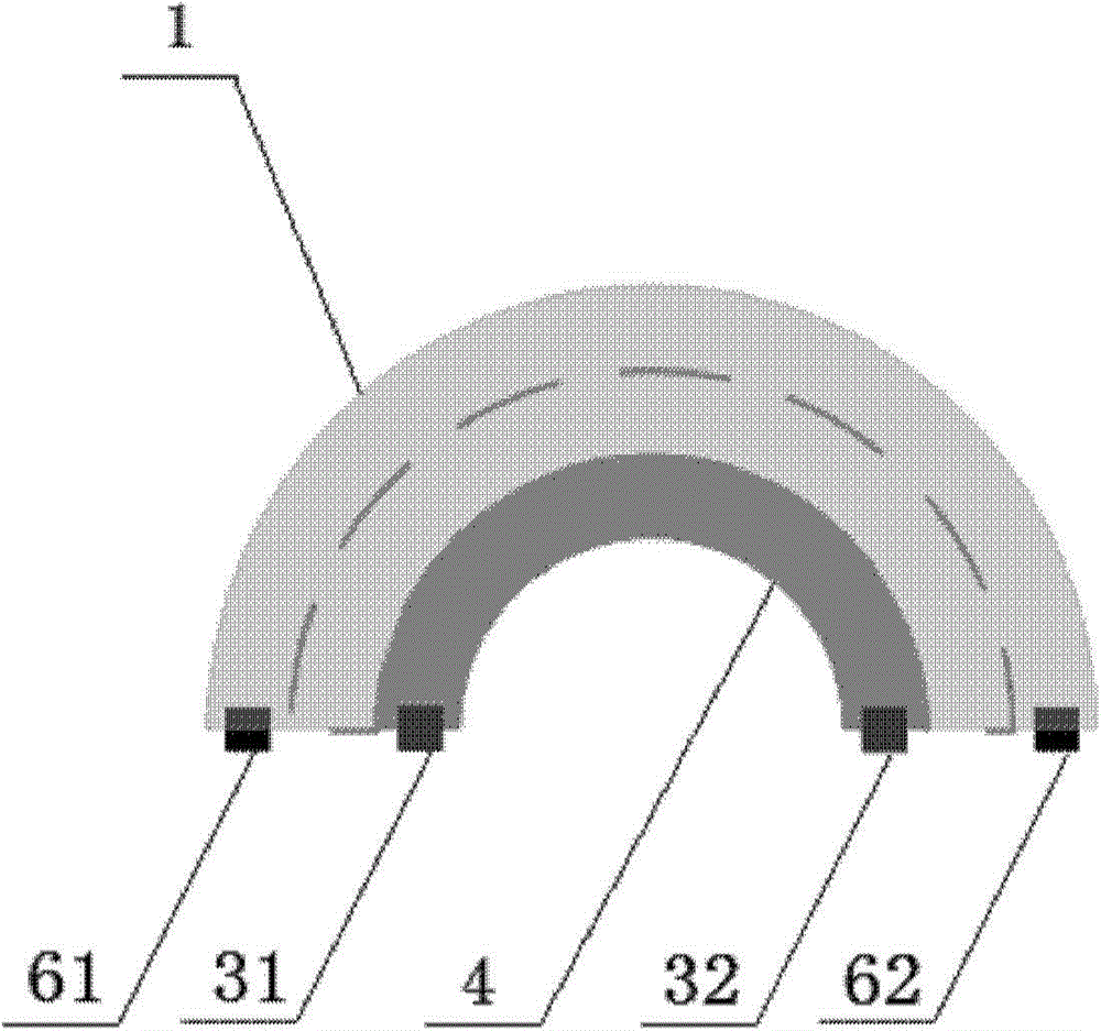
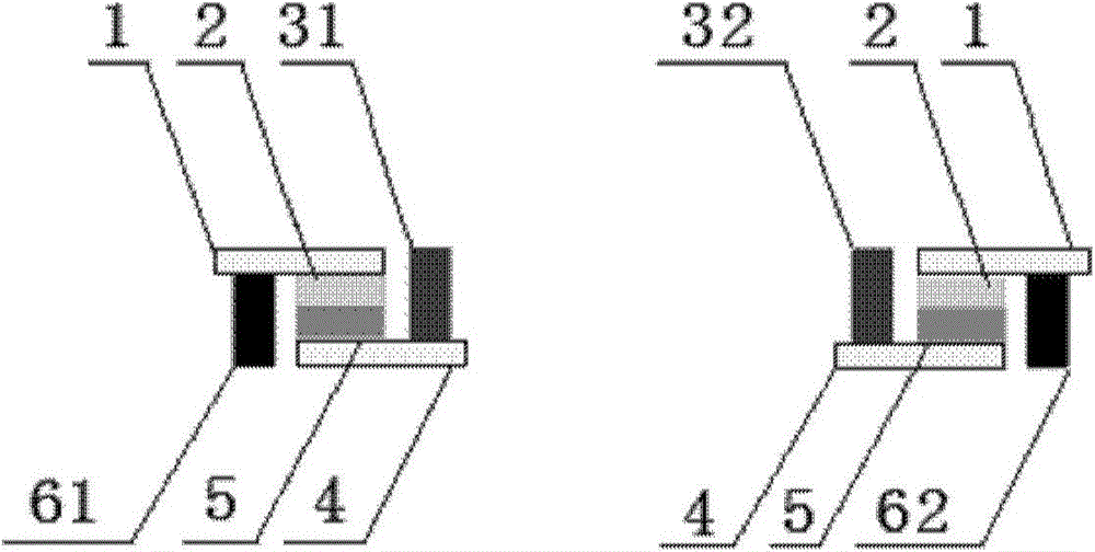
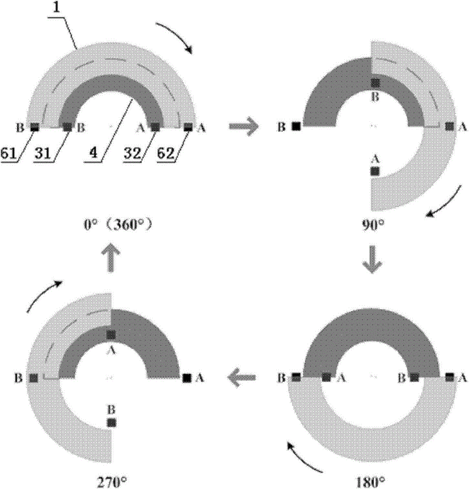
[0047] figure 1 and figure 2 A structural diagram of a rotating friction generator outputting constant current in the first embodiment of the present invention is shown respectively. Such as figure 1 , figure 2 as shown, figure 1 main view, figure 2 for figure 1 bottom view. In this embodiment, the rotating friction generator outputting a constant current includes: a first friction member 2, a pair of first conductive components 31, 32, a second friction member 5, and a pair of second conductive components 61, 62, the first The outer surface of a friction member 2 is provided with the first electrode 1 , and the outer surface of the second friction member 5 is provided with the second electrode 4 . In this embo...


PUM


Abstract

The invention discloses a rotary friction generator capable of outputting constant current, which comprises at least one first sub friction piece and at least one second friction piece, wherein the surfaces of the first sub friction piece and the second sub friction piece are provided with a first sub electrode and a second sub electrode respectively; the tail ends of the first sub friction piece and the second sub friction piece are provided with a first conductive component and a second conductive component respectively; the other surface of the first sub friction piece can carry out friction sliding with a constant speed in a clockwise or anti-clockwise direction relative to the other surface of the second sub friction piece. The rotary friction generator enables the two friction pieces to always keep contact friction through constant-speed circumferential motion, thereby generating inductive charge, driving flow of electrons in an external circuit, and realizing output of constant current through using the conductive component as a commutator. The rotary friction generator is simple in structure, convenient to realize and low in cost, can be used for providing power for an electronic device continuously and stably, and can also be used for providing power for a capacitor continuously and stably, and has very good social and economic benefits.

Description

technical field [0001] The invention belongs to the technical field of power generation, and in particular provides a rotating friction generator outputting constant current. Background technique [0002] Energy harvesting and conversion devices using nanotechnology, due to their unique self-generating and self-driving properties, are likely to play a key role in the manufacture and driving of self-powered nanodevices and nanosystem devices. Recently, researchers from various countries have received more and more attention. more and more attention. In 2006, the research group of Professor Wang Zhonglin from the Georgia Institute of Technology successfully realized the piezoelectric nanogenerator that uses zinc oxide nanowires to convert mechanical energy into electrical energy for the first time. Subsequently, based on the piezoelectric effect, various nanogenerators based on different materials and structures have been successively developed. Currently, the output power o...

Claims


Application Information

Patent Timeline
Patent Type & Authority Patents(China)
IPC IPC(8): H02N1/04
Inventor 张弛唐伟周桃韩昌报王中林
Owner BEIJING INST OF NANOENERGY & NANOSYST
Learn More