
Contact element for use in sliding contact

A technology for contacting elements and holding elements, applied to electrical components, connections, current collectors, etc., can solve problems that affect the performance or efficiency of electric motors or generators

Active Publication Date: 2014-07-09
ROBERT BOSCH GMBH
View PDF4 Cites 0 Cited by
  • Summary
  • Abstract
  • Description
  • Claims
  • Application Information

AI Technical Summary

Problems solved by technology

In the case of a commutator, the on or off position is thus changed via the position of the brushes on the slide, thereby affecting the performance or efficiency of the associated electric motor or generator

Method used


Image

  • Contact element for use in sliding contact
  • Contact element for use in sliding contact
  • Contact element for use in sliding contact

Examples


Embodiment Construction

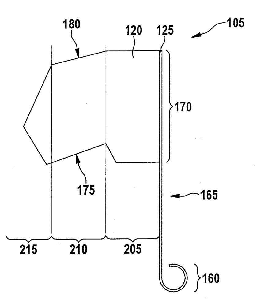
[0024] figure 1 A sliding contact 100 is shown, for example for commutating an electric motor or a generator. The sliding contact 100 includes a contact element 105 and a slideway 110 . In the illustrated embodiment, the slideway 110 is arcuate about a rotational axis 115 of the electric motor. In other embodiments, the sliding contact 100 can also be used on another device, for example a sliding contact for an antenna or a longitudinal stack. In other embodiments, the runner 110 also does not have to be curved, but can also extend, for example, in a plane.

[0025] The contact element 105 includes a brush 120 , a holding element 125 and an elastic element 130 . The brushes 120 are designed to bear against the slideway 110 . The cross-section of the brush 120 is generally rectangular, but other shapes are also possible. The abutment of the brush 125 on the slideway 110 is formed by a surface 135 which has a rising edge 140 and a falling edge 145 with respect to an assumed...


PUM


Abstract

The invention relates to a contact element for contacting with a slide path. The element has a brush supported against a slide path, an elongated fixing element, and a spring element. The elongated fixing element comprises a fixing segment and a holding segment to receive the brush on the mutually opposite ends. The spring element presses the brush against the slide path, so that an end of the brush elongated from the path moves close to the path according to an arc curve when the brush is used by friction by the path. The brush has a wear segment along the arc curve, on which an application surface of the brush is applied against the path, independent of wear of brush produced against the path.

Description

technical field [0001] The invention relates to a contact element for a sliding contact. In particular, the invention relates to the construction of a brush for a sliding contact provided for use on a rotating electrical machine. Background technique [0002] Sliding contacts serve to establish an electrical connection between a first element and a second element, which are arranged displaceably or rotatably relative to each other. In this case, the sliding contact comprises a runner on one element and a contact element on the other element, the contact element abutting against the runner, wherein both the runner and the contact element are Made of conductive material. Sliding contacts are used, for example, in the commutator of an electric motor. In this case the slideway is bent around the axis of rotation of the electric motor. [0003] The contact element usually includes a brush, a holding element and an elastic element, the brush rests on the slideway, the holding ...

Claims


Application Information

Patent Timeline
Patent Type & Authority Applications(China)
IPC IPC(8): H01R39/26
CPCH01R39/26H01R39/381H01R39/46
Inventor B.马齐斯
Owner ROBERT BOSCH GMBH
Learn More