Shift-by-wire system

A shift-by-wire, bus technology, used in transmission control, components with teeth, belts/chains/gears, etc., can solve problems such as high cost and system architecture

Inactive Publication Date: 2014-05-07
ZF FRIEDRICHSHAFEN AG
View PDF8 Cites 3 Cited by
  • Summary
  • Abstract
  • Description
  • Claims
  • Application Information

AI Technical Summary

Problems solved by technology

[0005] The disadvantage here is that such a sy

Method used


Image

  • Shift-by-wire system

Examples


Embodiment Construction

[0027] In the following description of the figures, the same elements or functions are denoted by the same reference numerals.

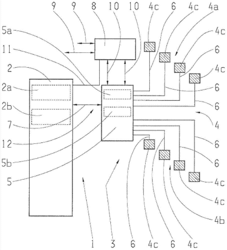
[0028] figure 1 An exemplary and schematic illustration shows a shift-by-wire system 1 with a transmission control unit or TCU 2 of a transmission control unit of a motor vehicle and with an actuating module or selector lever module 3 .

[0029] The gearshift modules 3 are designed to detect, by means of the actuating elements of each gearshift module 3 , in particular the gearshift lever, and the sensor device 4 the driver's desire regarding the operating state of the transmission, ie the driver's desire regarding the position of the gearshift lever. . In order to detect the selector lever position, the sensor system 4 has a plurality of sensors or receivers 4c arranged in each of the sensor arrays 4a,b, a redundant sensor array 4b being arranged next to the sensor array 4a for fail-safe detection. For clear reasons, in figure 1 The gear lever is...


PUM


Abstract

The invention relates to a shift-by-wire system (1) for a motor vehicle, having a transmission control device (2) and an actuating assembly (3) that is operatively connected to the transmission control device via an electric connection (7). The actuating assembly (3) is designed to generate a signal dependent on a driver request, which corresponds to a selector lever position, using a selector lever and at least one sensor (4c). The actuating assembly (3) further has a control unit (5), by means of which information based on the signal is communicated via the electric connection (7) to the transmission control device (2). The transmission control device (2) remotely monitors the control unit (5) in the actuating assembly (3) via the electric connection (7), said electric connection (7) being a common communication line for the signal-based information and the remote monitoring.

Description

technical field [0001] The invention relates to a shift-by-wire system, in particular for a motor vehicle, according to the preamble of claim 1 . Background technique [0002] In the prior art, a shift-by-wire system for a motor vehicle is sufficiently known, for example, from patent document DE 10 2005 008 383 A1, which describes an actuation for use with such a shift-by-wire device device. [0003] Systems of this type have an actuating module for interaction with the driver, for example a gear lever module, which is equipped for this purpose with a selector lever or selector lever. By means of the selector lever of the actuating unit and the associated sensor system, the driver's wishes regarding the operating state to be achieved by the transmission can be detected and transmitted to the transmission control unit. Systems of this type use a powerless, in particular purely electrical, method of transmission for the transmission, ie "by-wire". [0004] It is common in m...

Claims


Application Information

Patent Timeline
IPC IPC(8): F16H59/10F16H61/12F16H59/02F16H59/04
CPCF16H59/105F16H59/0204F16H59/044F16H61/12F16H2061/1208F16H2061/1224F16H2061/1268F16H2061/1284
Inventor 约瑟夫·哈本沙登
Owner ZF FRIEDRICHSHAFEN AG
Why Eureka
Try Eureka