Self-locking sliding rail

A self-locking slide rail and self-locking technology, applied in furniture parts, home appliances, drawers, etc., can solve the problems of the inner slide rail and the middle slide rail sliding out by themselves, and the slide rail cannot be locked.

Active Publication Date: 2014-05-14
WUXI JINGMEI PRECISION SLIDE +2
View PDF9 Cites 12 Cited by
  • Summary
  • Abstract
  • Description
  • Claims
  • Application Information

AI Technical Summary

Problems solved by technology

However, the existing three-section slide rail cannot lock the slide rail when the drawer is pushed back because there is no self-locking device. When non-human external forces such as tilting of the bearing surface and vibration occur, the inner slide rail and the The phenomenon that the middle slide rail slides out by itself

Method used


Image

  • Self-locking sliding rail
  • Self-locking sliding rail
  • Self-locking sliding rail

Examples


Embodiment Construction

[0021] The specific implementation manner of the present invention will be described below in conjunction with the accompanying drawings.

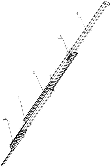
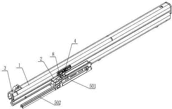
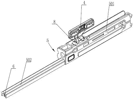
[0022] See figure 1 , figure 2 , the self-locking slide rail of the present invention comprises an inner slide rail 1, an outer slide rail 2 and a middle slide rail 3, the middle slide rail 3 is slidably arranged on the outer slide rail 2, and the inner slide rail 1 is slidably It is arranged on the middle slide rail 3; the inner slide rail 1 is fixedly connected with a dial block 4, and the outer slide rail 2 is fixedly equipped with a self-locking mechanism, and the self-locking mechanism includes a self-locking seat 5 fixedly connected to the outer slide rail 2 ,See image 3 , Figure 4 , Figure 5 , the self-locking seat 5 includes a self-locking arm 501, the bottom of the self-locking arm 501 is provided with a spring chute 5011, and the spring chute 5011 extends toward the outside of the self-locking arm 501 along the push-back ...


PUM


Abstract

A self-locking sliding rail comprises an inner sliding rail, an outer sliding rail and a middle sliding rail, wherein the middle sliding rail is arranged on the outer sliding rail, and the inner sliding rail is arranged on the middle sliding rail. The inner sliding rail is fixedly connected with a shifting block, the outer sliding rail is fixedly connected with a self-locking mechanism, and the self-locking mechanism comprises a self-locking seat. The self-locking seat comprises a self-locking arm, a spring chute is arranged at the bottom of the self-locking arm and extends towards the outside of the self-locking arm in the pushing-back direction of the self-locking sliding rail to form a fixing arm, a spring is arranged in the spring chute, one end of the spring is connected with one end of the fixing arm away from the self-locking arm, and the other end of the spring is connected with a sliding block. A rotating block and the sliding block are respectively in sliding connection with a pair of upper sliding ways and a pair of lower sliding ways. The rotating block is in rotating connection with the upper end of the sliding block, two limiting faces for controlling a rotating block rotation range are arranged on the sliding block and respectively located on two sides of the rotation center of the rotating block, a contact corner is arranged on the shifting block, and a clamping groove for accommodating the contact corner is arranged above the rotating block. The self-locking sliding rail can be automatically locked in a pushing-back state, and automatic slipping out of the sliding rail is avoided.

Description

technical field [0001] The invention relates to the technical field of slide rails, in particular to a three-section steel ball slide rail with a self-locking function. Background technique [0002] Slide rail is a kind of sliding tool widely used in daily life. It is usually used to connect two objects that can move relative to each other, such as drawers, rack-mounted servers, etc. The more common one is the three-section steel ball slide rail, which is usually installed on the drawer device for free pulling out and pushing back of the drawer device. Taking a drawer as an example, the three-section steel ball slide rail usually includes an outer slide rail, a middle slide rail and an inner slide rail. The outer slide rail is fixed on the support frame, and the inner slide rail is fixed on both sides of the drawer. It is connected between the outer slide rail and the inner slide rail to extend the movable range of the drawer, and enables the middle slide rail and the inner...

Claims


Application Information

Patent Timeline
Patent Type & Authority Applications(China)
IPC IPC(8): A47B88/04
Inventor 司彤
Owner WUXI JINGMEI PRECISION SLIDE
Why Eureka
Try Eureka