Jamb of sliding window

A sliding window and frame technology, applied in the direction of window/door frame, window/door, building components, etc., can solve the problems of unsatisfactory people, poor heat insulation effect of sliding windows, etc., and achieve good heat insulation effect

Inactive Publication Date: 2014-05-14
徐德
View PDF0 Cites 0 Cited by
  • Summary
  • Abstract
  • Description
  • Claims
  • Application Information

AI Technical Summary

Problems solved by technology

Because the existing sliding window frame is designed without heat insulation strip slots, the

Method used


Image

  • Jamb of sliding window

Examples


Example Embodiment

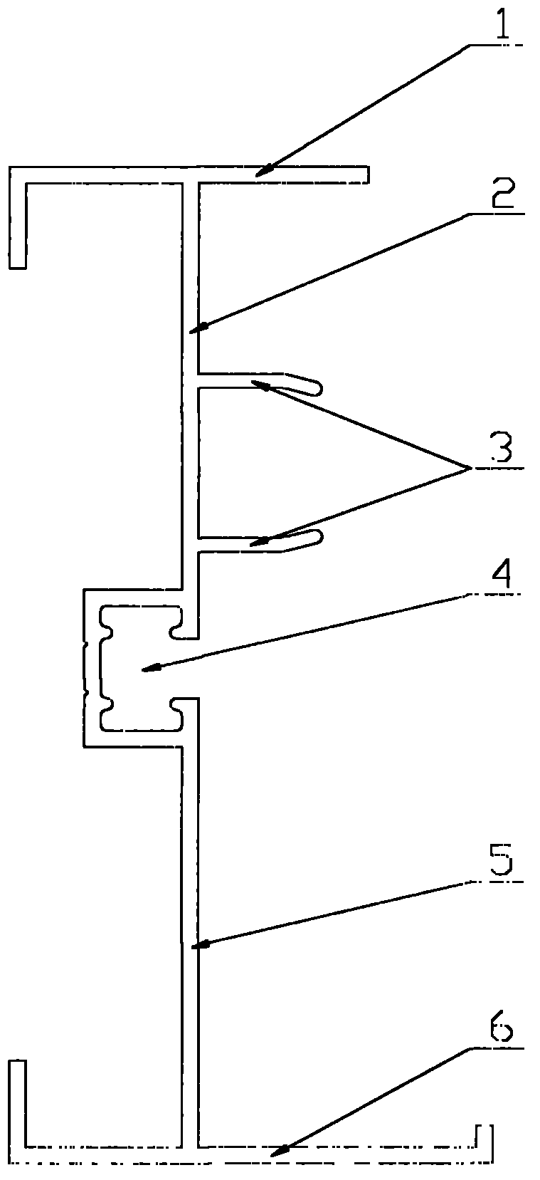
[0016] see figure 1 , the present invention relates to a sliding window frame, which includes an upper rail 1 and a lower rail 6, the middle part of the upper rail 1 is provided with an upper vertical rail 2 downward, and the middle part of the upper vertical rail 2 is set to the right There are baffles 3, there are two baffles 3, a lower vertical rail 5 is upwardly arranged in the middle of the lower crosspiece 6, and a heat insulation strip slot is arranged between the upper vertical rail 2 and the lower vertical rail 5 4.


PUM


Abstract

The invention discloses a jamb of a sliding window. The jamb comprises an upper transverse partition (1) and a lower transverse partition (6). An upper vertical partition (2) is downwardly arranged in the middle of the upper transverse partition (1), two barriers (3) are rightwards arranged in the middle of the upper vertical partition (2), a lower vertical partition (5) is upwardly arranged in the middle of the lower transverse partition (6), and a heat-insulation strip slot (4) is formed in a position between the upper vertical partition (2) and the lower vertical partition (5). The jamb of the sliding window has the advantages that the heat-insulation strip slot is formed in the position between the upper vertical partition and the lower vertical partition of the jamb, so that a good heat-insulation effect of the sliding window can be realized, and requirements of people can be met.

Description

(1) Technical field [0001] The invention relates to a sliding window frame and belongs to the technical field of building profiles. (2) Background technology [0002] In today's advocating economical growth and consumption patterns, in order to improve the airtightness, practicality and aesthetics of buildings, at present, aluminum sliding windows are generally used for windows on buildings. Because the existing sliding window frame adopts the slot design without heat insulation strips, the overall heat insulation effect of the sliding window is poor, which cannot meet people's needs. (3) Contents of the invention [0003] The object of the present invention is to overcome the above disadvantages and provide a sliding window frame with good heat insulation effect. [0004] The purpose of the present invention is achieved like this: [0005] A sliding window frame, comprising an upper crosspiece and a lower crosspiece, the middle part of the upper crosspiece is provided w...

Claims


Application Information

Patent Timeline
IPC IPC(8): E06B3/263E06B1/36
Inventor 徐德
Owner 徐德
Why Eureka
Try Eureka