
Electricity meter

A technology of electric meters and radio waves, which is applied in the field of electric meters, can solve problems such as inability to adjust the time and delay, and achieve the effect of solving inaccurate time adjustments

Inactive Publication Date: 2014-05-14
SUZHOU IND PRAK NEW HONGBO COMM TECH
View PDF4 Cites 3 Cited by
  • Summary
  • Abstract
  • Description
  • Claims
  • Application Information

AI Technical Summary

Problems solved by technology

However, with the increasing complexity of the system and the constraints of the communication environment, there are often problems such as delays and inability to calibrate the time in the process of correcting the time.

Method used


Image

  • Electricity meter

Examples


Embodiment Construction

[0012] The present invention will be described in detail below in conjunction with specific embodiments shown in the accompanying drawings. However, these embodiments do not limit the present invention, and any structural, method, or functional changes made by those skilled in the art according to these embodiments are included in the protection scope of the present invention.

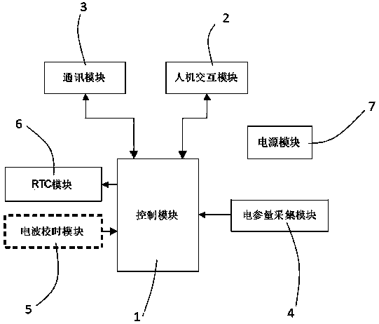
[0013] Such as figure 1 As shown, the electric meter of the present invention includes a control module 1 , a human-computer interaction module 2 , a communication module 3 , an electrical parameter collection module 4 , a radio wave timing module 5 , an RTC module 6 and a power supply module 7 .

[0014] The power supply module 7 is used to supply power to the entire electric meter system. The control module 1 is used to complete functions such as control and data analysis of the entire electric meter system, and has opposite input terminals and output terminals. The communication module 3 is intera...


PUM


Abstract

The invention provides an electricity meter comprising a control module which is used for completing functions of controlling, data analysis and the like of the whole electricity meter system; a communication module which is connected with the control module in an interaction way and used for realizing communication with other devices via wired and wireless modes; and an electric wave time-checking module which is connected with the input end of the control module and used for receiving a standard time signal transmitted via radio and completing time checking. The electric wave time-checking module is arranged in the electricity meter so that the whole electricity meter system has an automatic time-checking function and is maintained to be accurately synchronized with national standard time automatically. Therefore, a problem of inaccuracy in time checking caused by problems of time checking time-delay and communication in an electric power system and an energy consumption monitoring system is solved.

Description

technical field [0001] The invention relates to the field of electric meters, in particular to an electric meter with a radio wave time correction function. Background technique [0002] In the current power system and energy consumption monitoring system, in order to complete the measurement and monitoring of electric energy in various places and units, it is necessary to install a large number of electric meters; at the same time, all electric meters must be connected to the system through the grid system platform or energy consumption monitoring system platform . Again, the collection of electrical parameters in the system is related to time. In the traditional system, each device integrates its own real-time clock function, and all device clocks are broadcast by the system for time calibration. However, with the increasing complexity of the system and the constraints of the communication environment, there are often problems such as delays and inability to calibrate the...

Claims


Application Information

Patent Timeline
Patent Type & Authority Applications(China)
IPC IPC(8): G01R11/02G04G5/00G04R20/00
Inventor 徐以锋
Owner SUZHOU IND PRAK NEW HONGBO COMM TECH
Learn More