Wiring fixing cable clamp

A technology for fixing wire clamps and fixtures, which is applied in the direction of electrical components, etc., can solve the problems of inconvenient maintenance, large number of wire cards, and difficulty in distinguishing different lines, etc., and achieve the effects of convenient maintenance, saving efficiency, and good use effect

Inactive Publication Date: 2014-05-14
STATE GRID CORP OF CHINA +1
View PDF0 Cites 0 Cited by
  • Summary
  • Abstract
  • Description
  • Claims
  • Application Information

AI Technical Summary

Problems solved by technology

[0002] In circuit construction, especially indoors, the routing of wires is more common, but now wires are usually fixed by separate line cards. It brings a lot of inconvenience

Method used


Image

  • Wiring fixing cable clamp

Examples


Example Embodiment

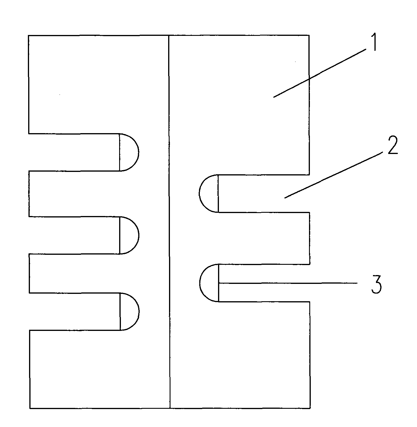
[0007] The embodiment will be described in detail with reference to the accompanying drawings. The embodiment of the present invention is a wiring fixing clamp, which includes a fixture 1 on which a plurality of U-shaped grooves 2 are provided. The U-shaped groove in this embodiment There is a wear pad 3 inside. When the present invention is in use, different lines are clamped into different U-shaped grooves, which can be marked beside the U-shaped groove. At the same time, it also saves the inconvenience of requiring multiple separate line cards to be fixed at the same position, and improves the line The construction efficiency of the routing, and facilitates future line maintenance.


PUM


Abstract

The invention discloses a wiring fixing cable clamp. The invention aims at designing the wiring fixing cable clamp. By using the cable clamp, the structure is reasonable and usage is convenient. A technical scheme of the invention is characterized in that the wiring fixing cable clamp comprises a clamping apparatus; the clamping apparatus is provided with a plurality of U-shaped grooves; wearing resistance pads are arranged in the U-shaped grooves. The structure is reasonable and a usage effect is good. Wiring efficiency is increased. Identification can be performed on different lines so that overhauling to the lines is convenient.

Description

Technical field: [0001] The invention relates to a wire routing device, in particular to a wire routing fixing clip often used in the circuit routing process. Background technique: [0002] In circuit construction, especially indoors, the routing of wires is more common, but now wires are usually fixed by separate line cards. It brings a lot of inconvenience. At the same time, due to the same appearance of the wiring lines, it is difficult to distinguish different lines, which also brings a lot of inconvenience to future maintenance. Invention content: [0003] The purpose of the present invention is to design a reasonable structure and easy to use cable fixing clip. [0004] The technical solution of the present invention is a wire routing fixing clamp, which includes a clamp, and is characterized in that multiple U-shaped grooves are provided on the clamp. An anti-friction pad is arranged in the U-shaped groove. [0005] The invention has reasonable structure, better ...

Claims


Application Information

Patent Timeline
IPC IPC(8): H02G3/02
Inventor 沈黎明石瑞涛吴望阳李广超
Owner STATE GRID CORP OF CHINA
Why Eureka
Try Eureka