
Wiper device

A wiper and wiper arm technology, which is applied in transportation and packaging, vehicle cleaning, vehicle maintenance, etc., can solve the problems of power wiper motors that do not record the swing of the wiper arm, so as to improve the layout and suppress the increase of the number Effect

Inactive Publication Date: 2014-05-14
MITSUBA CORP
View PDF8 Cites 11 Cited by
  • Summary
  • Abstract
  • Description
  • Claims
  • Application Information

AI Technical Summary

Problems solved by technology

In addition, in Patent Document 3, there is no description of a wiper motor that generates power for swinging the wiper arm.

Method used


Image

  • Wiper device
  • Wiper device
  • Wiper device

Examples


no. 1 approach )

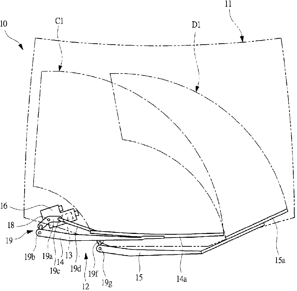
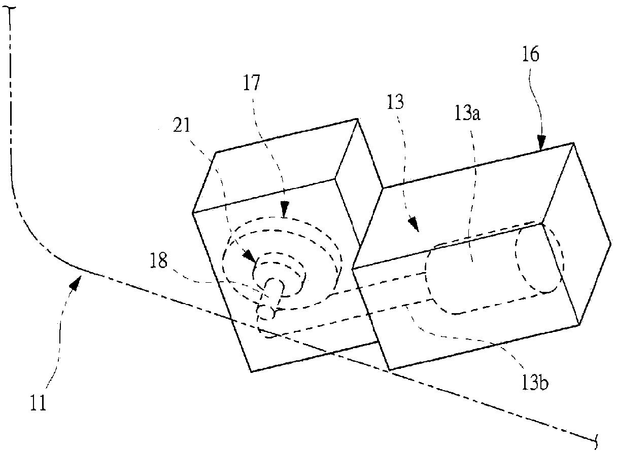
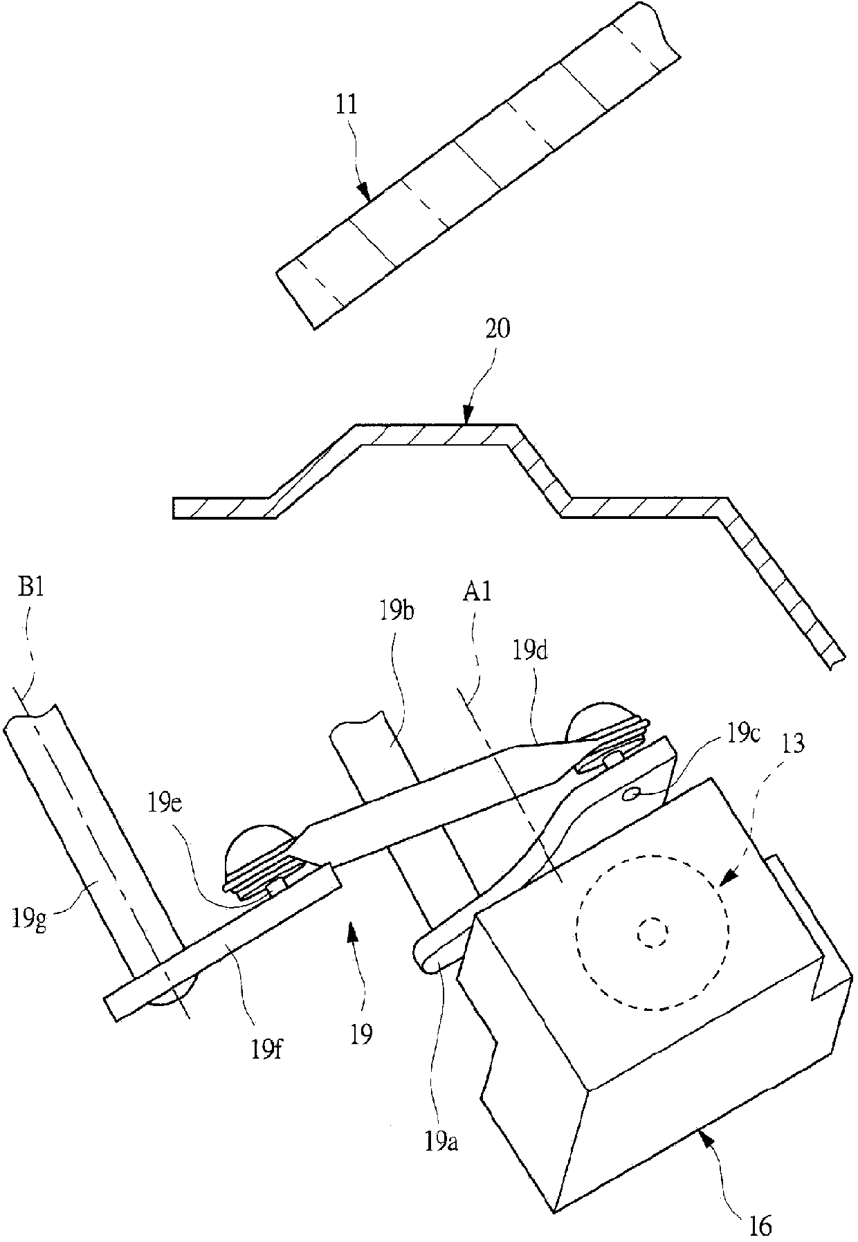
[0032] figure 1 It is a plan view schematically showing the front of the vehicle 10 on which the wiper device is mounted. figure 2 is schematically shown figure 1 A top view of the main part of the wiper device shown, image 3 is schematically shown figure 1 A side sectional view of the main part of the wiper device. Such as figure 1 As shown, a windshield 11 is provided on the front side of the interior so as to surround the interior of the vehicle 10 (to form the interior). The windshield 11 is provided so that its height is inclined in a direction where it becomes relatively higher as it moves toward the rear in the front-rear direction of the vehicle 10 . Here, the front-rear direction of the vehicle 10 refers to a direction along the traveling direction of the vehicle 10 . And, if figure 1 As shown, in a plane (not shown) along the horizontal direction of the vehicle 10, the middle part of the front glass 11 along the width direction of the vehicle 10 protrudes mo...

no. 2 approach )

[0055] Figure 4 is a plan view schematically showing the front of the vehicle 10 provided with the wiper device 12, Figure 5 is schematically shown Figure 4 A side sectional view of the main part of the wiper device 12 . Figure 4 with Figure 5 in, for and Figure 1 to Figure 3 shown constitute the same components, using and Figure 1 to Figure 3 same symbols and their descriptions are omitted. The wiper device 12 of the second embodiment is a so-called wiper motor 13 separately provided with a wiper motor 13 for swinging the wiper arm 14 on the cab side and a wiper motor 13 for swinging the wiper arm 15 on the passenger seat side. Wiper wiper device. The two wiper motors 13 are arranged at a predetermined interval on the left and right in the width direction of the vehicle 10 .

[0056] Among them, the wiper motor 13 that swings the wiper arm 14 on the cab side is the same as the wiper motor 13 that swings the wiper arm 15 on the passenger seat side, except that th...


PUM


Abstract

This wiper device has the following: a wiper arm (14) that swings about a rotating shaft (18); and a wiper motor (13) that produces the power to be transmitted to the rotating shaft (18). The wiper device is also provided with a power-transmission mechanism (19) that transmits power from the rotating shaft (18) to the wiper arm (14). Said power-transmission mechanism (19) is provided with the following: a linking member (19a) affixed to the rotating shaft (18); and a support shaft (19b) that supports the wiper arm (14) and is affixed to a point on the linking member (19a) offset from the rotating shaft (18). The support shaft (19b) is provided such that the coupling between the support shaft (19b) and the wiper arm (14) is located forwards of the front edge of the windshield (11). At least part of the wiper motor (13) is disposed in a region corresponding to the projection of the windshield (11). The wiper motor is thus disposed as far rearwards as possible in the vehicle with minimal increase in the number of components.

Description

technical field [0001] The present invention relates to a wiper device. The wiper device is configured to wipe the windshield of the vehicle by swinging a wiper arm disposed above the windshield by the power of a wiper motor disposed below the windshield of the vehicle. . Background technique [0002] In the prior art, the vehicle is equipped with a wiper device for wiping the attached matter on the windshield to ensure the driver's line of sight. The wiper device is configured to convert the rotational motion of the rotor of the wiper motor into the swing motion of the wiper arm. As forms for converting the rotational motion of the rotor of the wiper motor into the swinging motion of the wiper arm, there are known a direct drive type (DD) and a link type. First, a direct-acting wiper device has a worm formed on a rotor and a worm wheel meshing with the worm, and one end of a wiper arm is directly fixed to a rotating shaft serving as a rotation center of the worm wheel. S...

Claims


Application Information

Patent Timeline
Patent Type & Authority Applications(China)
IPC IPC(8): B60S1/08B60S1/24
CPCB60S1/245B60S1/0452B60S1/34
Inventor 岩崎幸二阿部纯
Owner MITSUBA CORP
Learn More