
Conveying channel provided with buffering bottle-storage mechanism and arranged between bottle blowing machine and filling machine

A conveying channel and bottle blowing machine technology, applied in the direction of conveyors, conveyor objects, transportation and packaging, etc., can solve the problems that cannot be fully discharged, bottles do not have enough storage space, etc., to achieve the effect of ensuring normal operation

Active Publication Date: 2014-05-21
JIANGSU NEWAMSTAR PACKAGING MACHINERY
View PDF6 Cites 14 Cited by
  • Summary
  • Abstract
  • Description
  • Claims
  • Application Information

AI Technical Summary

Problems solved by technology

The defect of the above conveying channel is that once the filling machine stops due to failure or other reasons, the bottle blowing machine will stop feeding embryos, but the formed bottles remaining in the blowing machine will die due to insufficient storage space on the conveying channel. cannot discharge all

Method used


Image

  • Conveying channel provided with buffering bottle-storage mechanism and arranged between bottle blowing machine and filling machine
  • Conveying channel provided with buffering bottle-storage mechanism and arranged between bottle blowing machine and filling machine
  • Conveying channel provided with buffering bottle-storage mechanism and arranged between bottle blowing machine and filling machine

Examples


Embodiment Construction

[0012] The present invention will be further described in detail below in conjunction with the accompanying drawings and preferred embodiments.

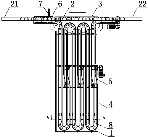
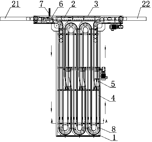
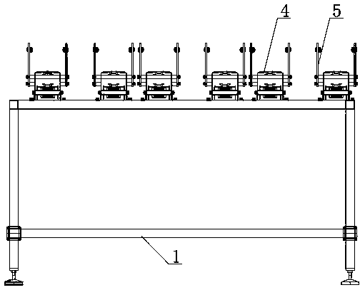
[0013] Such as figure 1 , figure 2 , image 3 , Figure 4 As shown, the conveying channel with a buffer bottle storage mechanism between the blow molding machine and the filling machine includes: a mounting frame 1, a conveying chain plate 2 is arranged on the mounting frame 1, and the bottle inlet end 21 of the conveying chain plate 2 is connected to the blowing bottle. The bottle machine is connected, the bottle outlet end 22 of the conveying chain plate 2 is connected with the filling machine, the conveying chain plate 2 is conveyed from the bottle blowing machine to the filling machine, and the installation frame 1 on both sides of the conveying chain plate 2 is provided with guardrails 3. One side of the conveyor chain plate 2 is provided with a buffer bottle storage mechanism. The buffer storage bottle chain plate 4, the e...


PUM


Abstract

The invention discloses a conveying channel provided with a buffering bottle-storage mechanism and arranged between a bottle blowing machine and a filling machine. The conveying channel comprises the buffering bottle-storage mechanism arranged on one side of a conveying chain board, wherein the buffering bottle-storage mechanism structurally comprises a buffering bottle-storage chain board which is arranged on an installation frame on one side of the conveying chain board and used for conveying bottles in a reciprocating and roundabout mode in the direction far away from the conveying chain board and the direction close to the conveying chain board, the bottle feeding end and the bottle discharging end of the buffering bottle-storage chain board are bent in an arc mode and communicated with the end portion of the bottle feeding end of the conveying chain board and the end portion of the bottle discharging end of the conveying chain board respectively, the buffering bottle-storage chain board is used for conveying bottles from the bottle feeding end of the buffering bottle-storage chain board to the bottle discharging end of the buffering bottle-storage chain board, and buffering bottle-storage guardrails are arranged at the positions, on two sides of the buffering bottle-storage chain board, of the installation frame; a guide baffle is further arranged on the outer side of the end portion of the bottle feeding end of the conveying chain board, and a driving device drives the guide baffle to be capable of enabling bottles entering from the bottle feeding end of the conveying chain board to be guided to the buffering bottle-storage chain board. The conveying channel has the advantages that after the filling machine is switched off, all bottles remaining in the bottle blowing machine can be discharged.

Description

technical field [0001] The invention relates to a conveying channel with a buffer bottle storage mechanism between a bottle blowing machine and a filling machine in the field of filling machinery. Background technique [0002] There is a conveying channel for conveying empty bottles between the blow molding machine and the filling machine. The traditional conveying channel includes: a mounting frame, and a conveying chain plate is arranged on the mounting frame, and the bottle inlet end of the conveying chain plate is connected with the blowing machine. , the bottle outlet end of the conveying chain plate is connected with the filling machine, and the conveying chain plate is transported from the bottle blowing machine to the filling machine, and the mounting frames on both sides of the conveying chain plate are provided with guardrails. When working, the bottle blown out by the blow molding machine is conveyed to the conveying chain plate of the conveying channel, and the c...

Claims


Application Information

Patent Timeline
Patent Type & Authority Applications(China)
IPC IPC(8): B65G47/52B65G17/40
Inventor 陆鹏飞季汪超
Owner JIANGSU NEWAMSTAR PACKAGING MACHINERY
Learn More