Set bar mechanism

A lock tongue and lock tongue groove technology, applied in the direction of building locks, building structures, buildings, etc., can solve the problems of high noise and low safety of the lock tongue, and achieve the purpose of ensuring safety, increasing service life, and ensuring normal rest. Effect

Active Publication Date: 2014-05-21
WONLY SECURITY & PROTECTION TECH CO LTD
View PDF6 Cites 2 Cited by
  • Summary
  • Abstract
  • Description
  • Claims
  • Application Information

AI Technical Summary

Problems solved by technology

[0006] The technical problem to be solved by the present invention is that the deadbolt mechanism in the prior art is noisy and low in safety, and a deadbolt mechanism with low noise and high safety is provided

Method used


Image

  • Set bar mechanism
  • Set bar mechanism
  • Set bar mechanism

Examples


Embodiment Construction

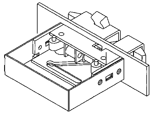
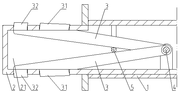
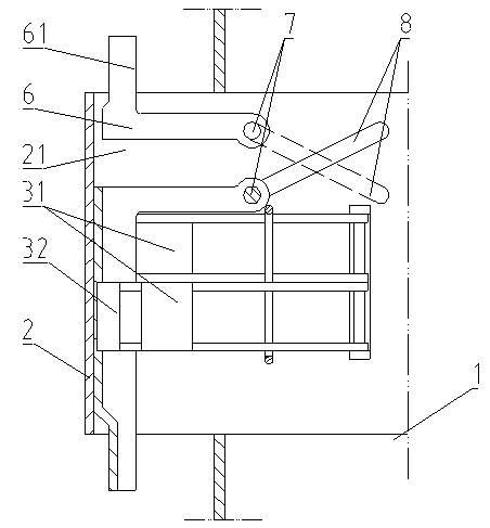
[0046] Such as Figure 2-5 Shown is an embodiment of the bolt mechanism of the present invention. The bolt mechanism is arranged in the lock casing 1 of the door lock and can move back and forth relative to the lock casing 1 in a direction perpendicular to the lock casing panel, so as to enter and exit the bolt groove provided on the door frame; including: the bolt 2 , a set of pressing components, and a push-pull mechanism corresponding to the pressing components. The inside of the lock tongue 2 is formed with a housing chamber 21; the pressing assembly is arranged in the housing chamber 21, including a rotating shaft 4 fixedly positioned on the fixing plate of the lock tongue 2, which is rotatably arranged in the housing chamber 21. The connecting rod 3 in the accommodating chamber 21 and the protrusion 31 fixedly arranged on the surface of the connecting rod 3 facing the moving direction of the door leaf close to the lock tongue 2 and protruding closer to the lock tongue t...


PUM


Abstract

A set bar mechanism comprises a set bar (2), a set of press-fit components and a push-pull mechanism corresponding to the press-fit components. A containing cavity (21) is formed in the set bar (2). The press-fit components are arranged in the containing cavity (21) and synchronously move in the direction perpendicular to a lock shell panel along with the movement of the set bar (2). The push-pull mechanism is arranged between a lock shell (1) and the press-fit components and drives the press-fit components to extend out of or retract into the containing cavity (21) in the movement direction of a door leaf when the set bar moves in the direction perpendicular to the lock shell panel. The press-fit components are closely attached to the side edge of a slot hole of a set bar slot when the set bar enters the set bar slot. The set bar mechanism is low in noise and high in safety.

Description

technical field [0001] The invention relates to the technical field of hardware manufacturing, in particular to a lock tongue mechanism. Background technique [0002] In order to increase the safety performance of the door lock and prevent the door lock from being opened illegally, the prior art generally locks the door by setting the deadbolt. A crab pincer type glass door lock, the door lock includes a lock shell, a lock shell, a lock cylinder with a puller, a locking mechanism and a positioning post for positioning the locking mechanism, the rear parts of the lock shell and the lock shell are respectively arranged There is a splint formed by bending a slat, and a lock tongue is provided at the front end of the locking mechanism. The lock tongue includes two tongue plates, a crab claw type knuckle and a return spring sandwiched between the two tongue plates, and the two hooks Tongues are set back to back and the rear hinged device is between the two tongue plates, and the...

Claims


Application Information

Patent Timeline
Patent Type & Authority Applications(China)
IPC IPC(8): E05B15/10
Inventor 王斌坚
Owner WONLY SECURITY & PROTECTION TECH CO LTD
Why Eureka
Try Eureka