Friction ring and multi-synchronization structure

A synchronization device and friction ring technology, which is applied in the field of friction rings, can solve the problems that the three-cone synchronization device is too large, the two-phase synchronization device cannot produce friction capacity, etc., and achieve the effect of fast synchronization and simple structure

Active Publication Date: 2014-05-21
HOERBIGER ANTRIEBSTECHN HLDG
View PDF5 Cites 1 Cited by
  • Summary
  • Abstract
  • Description
  • Claims
  • Application Information

AI Technical Summary

Problems solved by technology

The disadvantage of this case is that for some applications the three-cone synchronizer is oversized and the two-phase synchronizer does not generate enough friction capacity

Method used


Image

  • Friction ring and multi-synchronization structure
  • Friction ring and multi-synchronization structure
  • Friction ring and multi-synchronization structure

Examples


Embodiment Construction

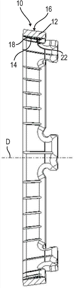
[0025] figure 1 10 shows a friction ring 10 which has an annular support core 12 made of metal, preferably sheet metal. The support core 12 has an inner surface 14 and an outer surface 16 which are configured as conical surfaces running parallel. The support core 12 is thus a cone ring.

[0026] Furthermore, a friction lining 18 is fastened to the bearing core 12 , here on the inner surface 14 , which thus simultaneously defines a contact surface for the friction lining 18 . On its radial inner side, the friction lining 18 forms a friction surface 22 which is arranged on the side of the friction lining 18 opposite the surface 14 .

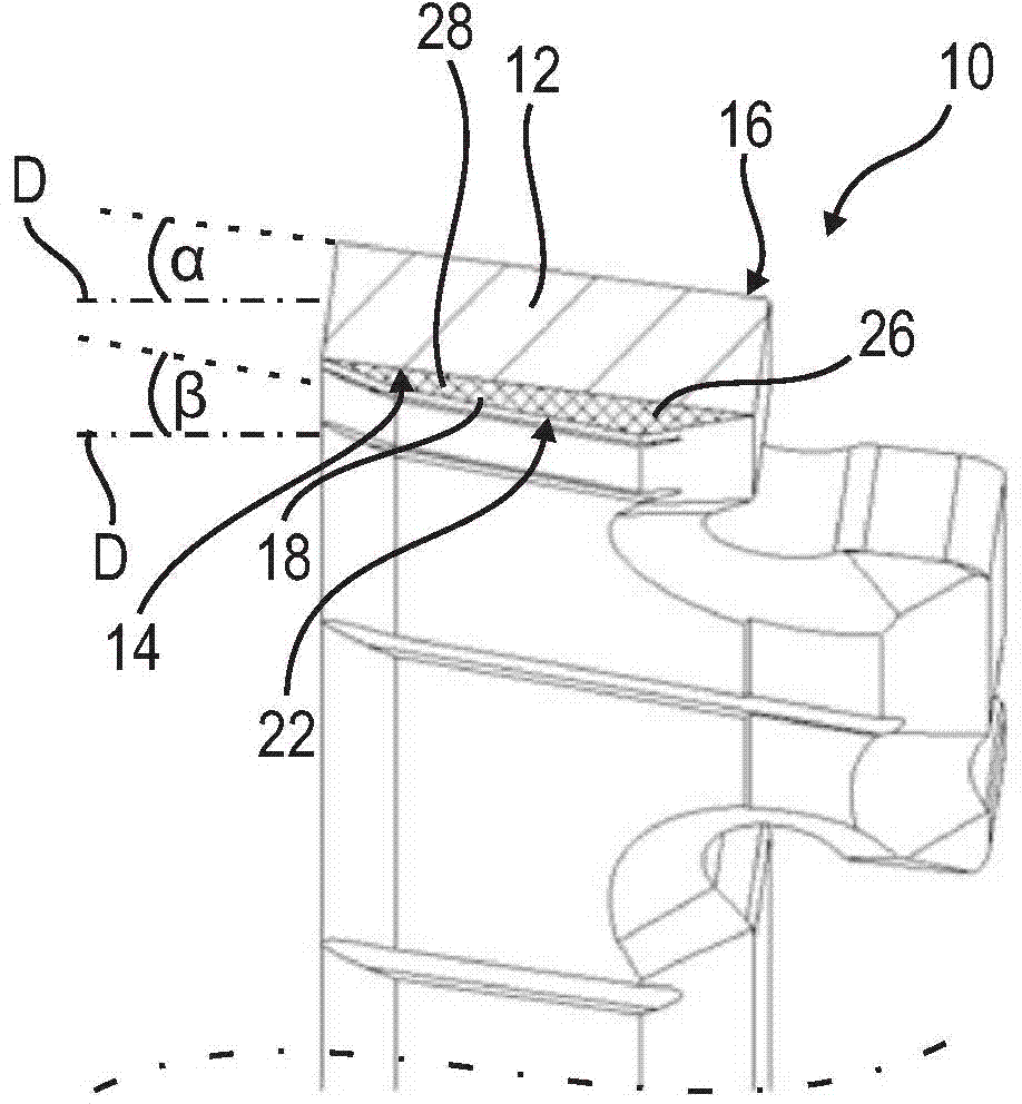
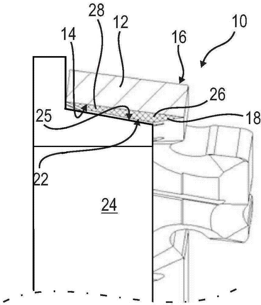
[0027] Figure 2a and 2b A detail view showing the fastening and configuration of the friction lining 18 on the bearing core 12 .

[0028] Figure 2a As can be seen in , the friction lining 18 is bounded in longitudinal section by the contact surface or surface 14 of the support core 20 and the friction surface 22 opposite the contact surface...


PUM


Abstract

The invention relates to a friction ring for three-folded multi-synchronization structure of a gearbox. The friction ring (10) has an annular support core (12) including an internal lateral surface (14) and an external lateral surface (16) and a friction lining (18). The internal lateral surface (14) and the external lateral surface (16) form a conical contact surface with the friction lining (18) fixed thereon. The friction lining (18) has a friction surface (22) for contact with a corresponding surface and has a wedge-shaped cross-sectional area defined by the contact area and the friction surface in a vertical profile view. In addition, the invention further relates to a multi-synchronization structure employing the friction ring.

Description

technical field [0001] The invention relates to a friction ring for a multi-cone synchronizer of a transmission and a multi-cone synchronizer with such a friction ring. Background technique [0002] Friction rings for multi-cone synchronizers are known from the prior art. The friction rings can be used, for example, to mutually compensate or synchronize the rotational speeds of the rotatable parts. Friction rings usually have a bearing core with friction linings, which are fastened to at least one surface of the bearing core. The friction lining defines a friction surface via which it interacts with a corresponding surface of a further friction element, preferably a further friction ring, in order to achieve synchronization. A friction lining and another friction element are called a friction pair. Furthermore, it is known from the prior art that the angle formed between the friction pair and the axis of rotation of the friction ring is a key factor influencing the fricti...

Claims


Application Information

Patent Timeline
Patent Type & Authority Applications(China)
IPC IPC(8): F16D23/04F16D13/66
CPCF16D23/025F16D2023/0681
Inventor 托马斯·伯梅约尔格·勒夫勒
Owner HOERBIGER ANTRIEBSTECHN HLDG
Why Eureka
Try Eureka