Friction ring and multi-cone synchronizer
A synchronization device and friction ring technology, which is applied in the field of friction rings, can solve the problems that the three-cone synchronization device is too large, the two-phase synchronization device cannot produce friction capacity, etc., and achieve the effect of fast synchronization and simple structure
- Summary
- Abstract
- Description
- Claims
- Application Information
AI Technical Summary
Problems solved by technology
Method used
Image
Examples
Embodiment Construction
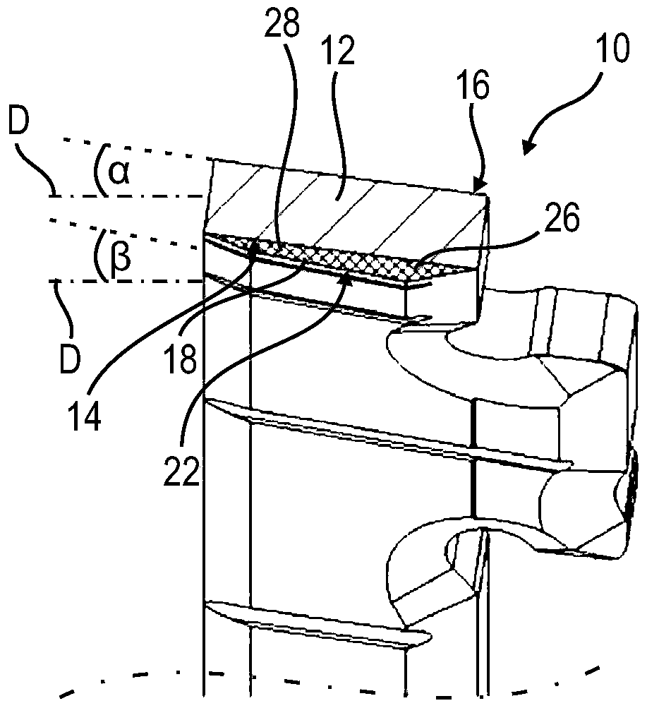
[0025] figure 1 10 shows a friction ring 10 which has an annular support core 12 made of metal, preferably sheet metal. The support core 12 has an inner surface 14 and an outer surface 16 which are configured as conical surfaces running parallel. The support core 12 is thus a cone ring.
[0026] Furthermore, a friction lining 18 is fastened to the bearing core 12 , here on the inner surface 14 , which thus simultaneously defines a contact surface for the friction lining 18 . On its radial inner side, the friction lining 18 forms a friction surface 22 which is arranged on the side of the friction lining 18 opposite the surface 14 .
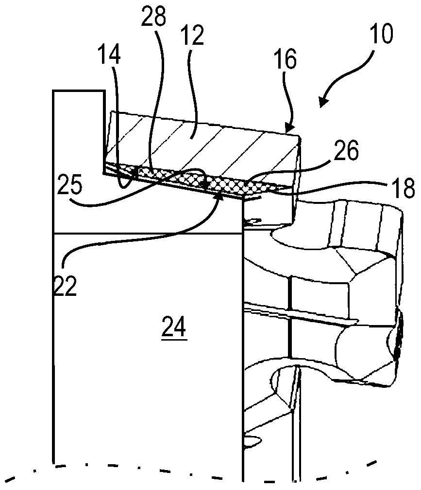
[0027] Figure 2a with 2b A detail view showing the fastening and configuration of the friction lining 18 on the bearing core 12 .
[0028] Figure 2a As can be seen in , the friction lining 18 is bounded in longitudinal section by the contact surface or surface 14 of the support core 20 and the friction surface 22 opposite the contact surfac...
PUM
 Abstract
Description
Claims
Application Information
 - R&D
- Intellectual Property
- Life Sciences
- Materials
- Tech Scout
- Unparalleled Data Quality
- Higher Quality Content
- 60% Fewer Hallucinations
Browse by: Latest US Patents, China's latest patents, Technical Efficacy Thesaurus, Application Domain, Technology Topic, Popular Technical Reports.
© 2025 PatSnap. All rights reserved.Legal|Privacy policy|Modern Slavery Act Transparency Statement|Sitemap|About US| Contact US: help@patsnap.com


