Supporting device for pneumatic rotating platform
A technology of supporting device and rotating platform, applied in machine/stand, supporting machine, mechanical equipment, etc., can solve the problems of high cost, large quality, complex structure, etc., to improve quality and efficiency, stable performance, good supporting effect Effect
- Summary
- Abstract
- Description
- Claims
- Application Information
AI Technical Summary
Problems solved by technology
Method used
Image

Examples
Embodiment Construction
[0011] Combine below figure 1 Specific description embodiment:
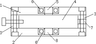
[0012] A support device of a pneumatic rotary platform, the support device of the pneumatic rotary platform includes an upper cover plate 1 and a lower cover plate 2, a vertical plate 3 is arranged between the upper cover plate 1 and the lower cover plate 2, the The upper cover plate 1, the lower cover plate 2 and the vertical plate 3 are combined to form a cavity 4, the upper cover plate 1 is provided with a through hole 5, and the through hole 5 is provided with a bearing sleeve 6. Offer cylinder inlet hole 7 on the vertical plate 3. A shaft hole 8 is opened on the lower cover plate 2 , and a bearing sleeve 6 is arranged in the shaft hole 8 .
[0013] In specific use, a rotating shaft is arranged in the cavity, the upper end of the rotating shaft passes through the through hole and is connected with a rotating plane, and the other end of the rotating shaft is connected with the lower cover plate through the s...
PUM
 Abstract
Description
Claims
Application Information
 - R&D
- Intellectual Property
- Life Sciences
- Materials
- Tech Scout
- Unparalleled Data Quality
- Higher Quality Content
- 60% Fewer Hallucinations
Browse by: Latest US Patents, China's latest patents, Technical Efficacy Thesaurus, Application Domain, Technology Topic, Popular Technical Reports.
© 2025 PatSnap. All rights reserved.Legal|Privacy policy|Modern Slavery Act Transparency Statement|Sitemap|About US| Contact US: help@patsnap.com