Drawer type tool cabinet
A toolbox and drawer-type technology, applied in drawers, furniture parts, household appliances, etc., can solve the problems of large stress concentration, short service life, and easy damage to the drawer at the connection between the drawer and the cabinet, so as to reduce the stress concentration, The effect of prolonging the service life and not easy to damage
- Summary
- Abstract
- Description
- Claims
- Application Information
AI Technical Summary
Problems solved by technology
Method used
Image

Examples
Embodiment 1
[0020] In order to make the accompanying drawings clear, only a drawer toolbox with one drawer 2 is shown in the accompanying drawings. During specific use, multiple drawers 2 can be provided to make the drawer toolbox more convenient to use.
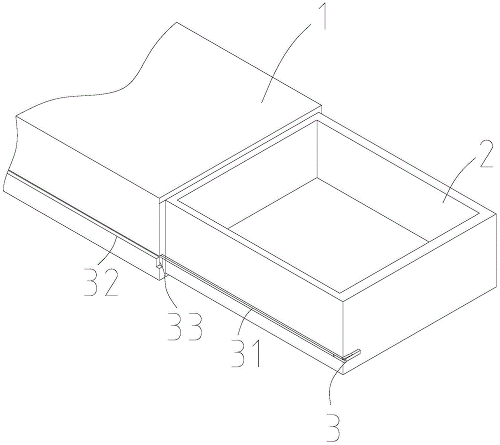
[0021] Below in conjunction with accompanying drawing, drawer type tool box of the present invention will be further described. like figure 1 , figure 2 , Figure 5 , Image 6 As shown, the drawer 2 cabinet includes a cabinet body 1 and a drawer 2 arranged on the cabinet body 1. The cabinet body 1 is also provided with a protrusion 5 for restricting the drawer 2 from being completely drawn out. The protrusion 5 can be welded It is arranged on the cabinet body 1 by means of a detachable connection, and a support for supporting the drawer 2 is provided between the cabinet body 1 and the drawer 2 after the drawer 2 is completely drawn out. Institution 3.
[0022] The support mechanism 3 includes a support rod 31 arranged on the drawe...
Embodiment 2
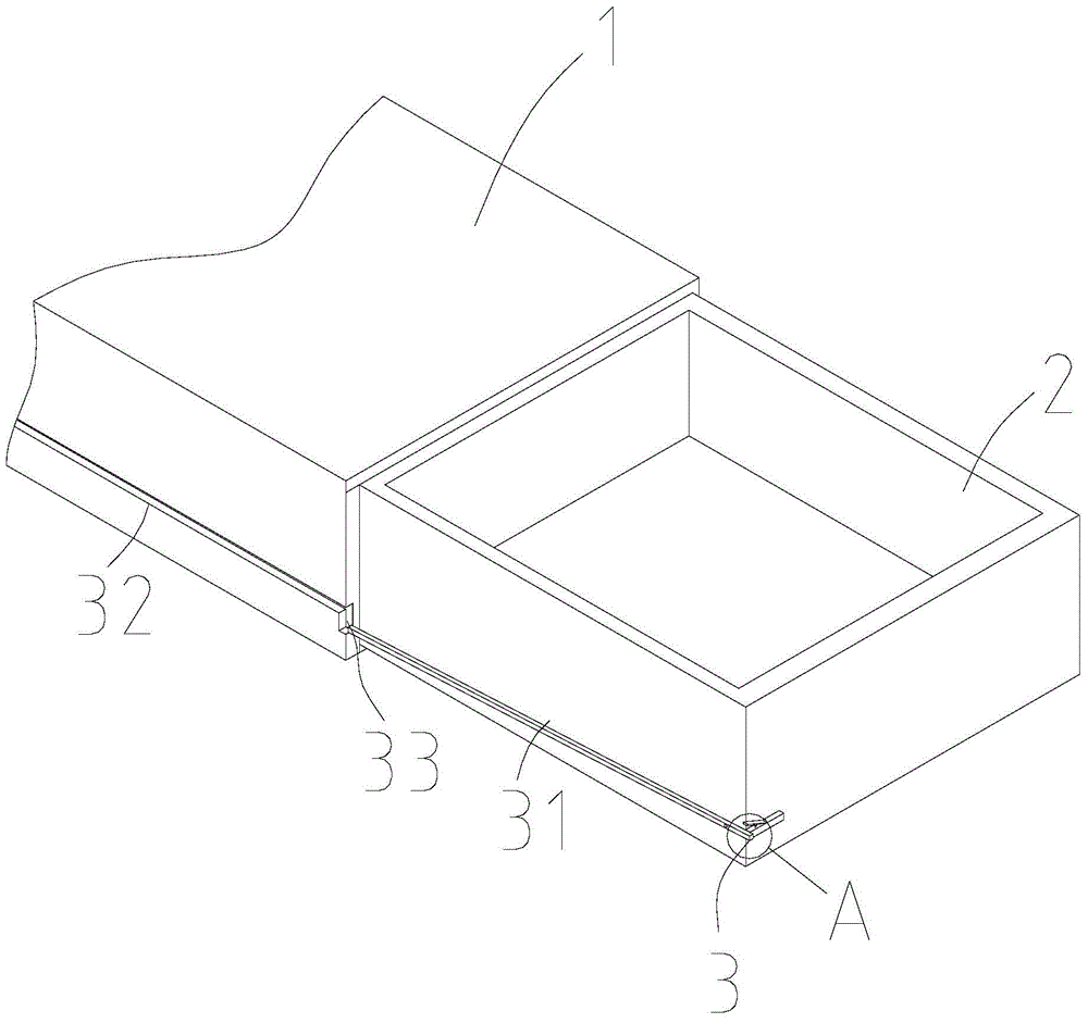
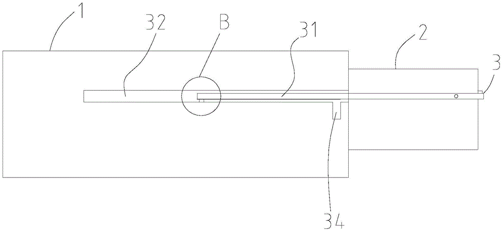
[0028] The difference between this embodiment and Embodiment 1 is that: image 3 , Figure 4 As shown, the support mechanism 3 includes a support rod 31 arranged on the drawer 2, a chute 32 arranged on the cabinet body 1, and a chute 32 arranged on the cabinet body 1 to communicate with the chute 32 for positioning the support rod 31 after the drawer 2 is pulled out. The positioning groove 34 of the support rod 31 is arranged on the drawer 2 in turn, and the other end of the support rod 31 is provided with a positioning post 35 perpendicular to the axial direction of the support rod 31, and the positioning post 35 can be screwed. Or the welding method is arranged on the support rod 31, and the support rod 31 and the positioning column 35 are slidably arranged in the chute 32, and the positioning groove 34 is adapted to the positioning column 35 arranged at the end of the support rod 31, by setting Positioning column 35, and make positioning column 35 cooperate with positionin...
PUM
 Abstract
Description
Claims
Application Information
 - Generate Ideas
- Intellectual Property
- Life Sciences
- Materials
- Tech Scout
- Unparalleled Data Quality
- Higher Quality Content
- 60% Fewer Hallucinations
Browse by: Latest US Patents, China's latest patents, Technical Efficacy Thesaurus, Application Domain, Technology Topic, Popular Technical Reports.
© 2025 PatSnap. All rights reserved.Legal|Privacy policy|Modern Slavery Act Transparency Statement|Sitemap|About US| Contact US: help@patsnap.com