Eureka AIR delivers breakthrough ideas for toughest innovation challenges, trusted by R&D personnel around the world.

Electric shoe polisher

An electric brush and shoe polish technology, applied in the direction of cleaning boots and shoes, cleaning equipment, household appliances, etc., can solve the problems of long time, waste of shoe polish, low work efficiency, etc.

Inactive Publication Date: 2014-05-28
宁波清士洁电器科技有限公司
View PDF8 Cites 5 Cited by
  • Summary
  • Abstract
  • Description
  • Claims
  • Application Information

AI Technical Summary

Problems solved by technology

[0002] Leather shoes are commonly used items in people's lives. The cleaning and maintenance of leather shoes is more troublesome. At present, it is generally carried out by manual wiping. It is necessary to dedust, oil, and polish the leather shoes in sequence. It is necessary to use a brush to remove the dust on the surface of the leather shoes. , and then use a brush to brush the shoe polish onto the surface of the leather shoes, and then use cotton cloth to polish the surface of the leather shoes. In this way, the operation is more troublesome and the work efficiency is low. Moreover, since the dust removal, oiling, and polishing operations are all carried out manually, it is necessary to pass Wipe the leather shoes by hand, so that the operator's hand is easy to get shoe polish, which brings inconvenience to the operator
[0003] Some electric tools for wiping and nursing leather shoes have also appeared on the market now, as the Chinese patent of patent No. 201010111675.5, which discloses a kind of electric shoe polisher, and this electric shoe polisher includes oiling brush head, polishing brush head and shoe polish The bin body, the oiling brush head and the polishing brush head are respectively set at both ends of the body, and the shoe polish bin body is set in the body. When the electric shoe polisher is working, first open the shoe polish bin cover, and then press the shoe polish bin body in the body with your fingers , the shoe polish in the shoe polish compartment is squeezed onto the oiling brush head. At this time, the oiling brush head is driven by the gear motor to rotate to oil the leather shoes, that is, the shoe polish is applied to the surface of the leather shoes through the oiling brush head, and oiled After completion, the leather shoe surface is polished by the direct current motor to drive the polishing brush head to rotate, but this electric shoe polisher still has the following deficiencies in actual use: 1. The oiling brush head and the polishing brush head are respectively located at two sides of the body. When using the end, you need to use the oiling brush head to oil first, and then use the polishing brush head to polish after the oiling is completed. In this way, it takes a long time and makes the work efficiency low; 2. The oiling brush head and The polishing brush heads are all flat brush heads. When the flat brush head rotates, it will drive the shoe polish on the surface of the leather shoes to rotate together, so that it is easier to make the shoe polish splash out due to centrifugal force, resulting in waste of shoe polish; The shoe polish of the same color can be used, and the oiling brush head and the polishing brush head cannot be replaced, so that the electric shoe brush can only be used for wiping and caring for leather shoes of the same color, but cannot be used for wiping and caring for shoes of different colors. Inconvenient; 4. Since it is necessary to press the shoe polish bin with your fingers to squeeze the shoe polish onto the oiling brush head, on the one hand, you need to open and close the shoe polish bin cover, which is troublesome, and the strength when pressing the shoe polish bin with your fingers is not good Grasp, so that the amount of shoe polish extrusion is not easy to control, and it is easy to cause waste of shoe polish

Method used


Image

  • Electric shoe polisher
  • Electric shoe polisher
  • Electric shoe polisher

Examples


Embodiment 1

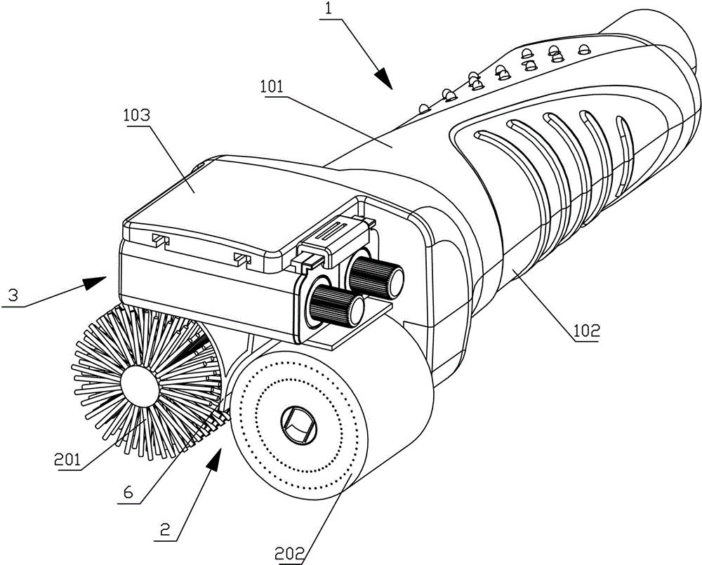
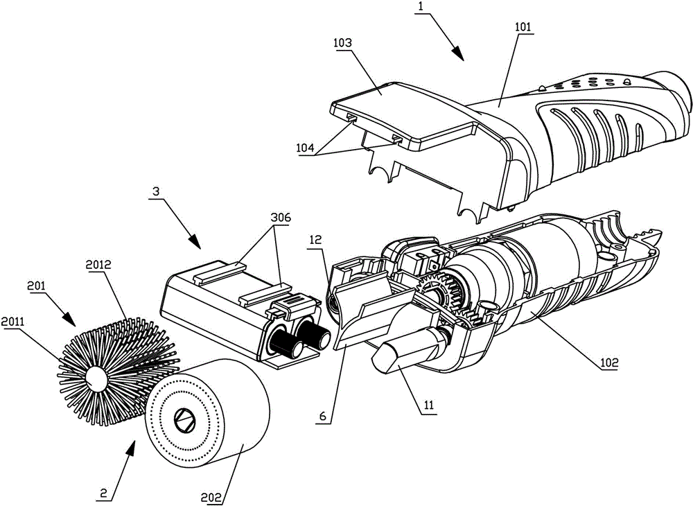
[0031] Depend on figure 1 , figure 2As shown, the electric shoe brushing device of the present invention includes a handle portion 1, a brush body 2 and an oil storage device 3, and the brush body 2 includes a shoe polish brush roller 201 and a polishing brush roller 202, and the shoe polish brush roller 201 and the polishing brush roller 202 and the oil storage device 3 are all arranged at one end of the handle part 1, the axes of the shoe polish brush roller 201 and the polishing brush roller 202 are parallel, the shoe polish brush roller 201 and the polishing brush roller 202 are horizontally arranged in parallel, and the oil storage device 3 is arranged on the shoe polish brush roller Above the roller 201, one end of the handle portion 1 is provided with a mounting plate 103, the mounting plate 103 is located above the shoe polish brush roller 201 and the polishing brush roller 202, and the lower surface of the mounting plate 103 is provided with two extending along the l...

Embodiment 2

[0039] Compared with the first embodiment, this embodiment differs in that the installation method of the oil storage device 3 is different, by Figure 8 , Figure 9 As shown, one end of the handle portion 1 is provided with a first support portion 105 extending along the width direction of the handle portion 1, and the end of the mounting plate 103 away from the handle portion 1 is provided with a downwardly extending limiting plate 107, and the limiting plate 107 The lower end of the lower end is provided with the second support part 106 parallel to the first support part 105, and the installation plate 103, the limit plate 107, the first support plate 105, and the second support plate 106 form a space for accommodating the oil storage device 3. For the oil storage device 3 , insert the oil storage device under the mounting plate 103 along the width direction of the handle part 1 .

Embodiment 3

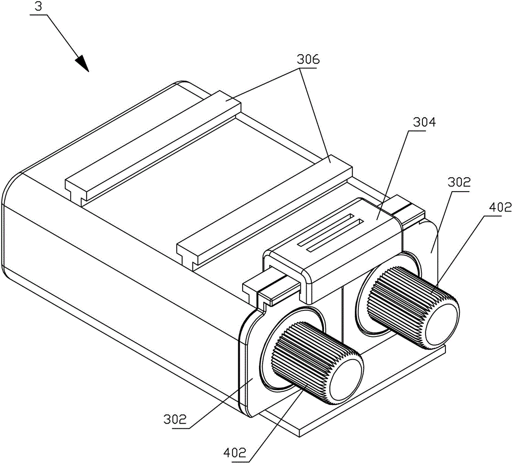
[0041] Compared with Embodiment 1, this embodiment differs in that the structure and installation method of the oil storage device are different. Figure 10 , Figure 11 As shown, the mounting plate 103 is provided with a mounting hole 108, and the oil storage device 3 is fixed in the mounting hole 108, by Figure 12 , Figure 13 , Figure 14 , Figure 15 As shown, the cavity opening 303, the cavity cover 302, and the knob 402 are located on the upper surface of the oil storage device 3, the screw rod 4 is vertically arranged, the pressure plate 403 and the limit plate 401 are horizontally arranged, the opening 5 is located at the bottom of the cavity 301, and the baffle plate 6 is a flat plate, and the baffle plate 6 is fixed on the bottom of the oil storage device 3. The baffle plate 6 is arranged between the shoe polish brush roller 201 and the polishing brush roller 202. In addition, the pressure plate 403 is provided with a seal fitting with the inner wall of the cavit...


PUM


Abstract

The invention discloses an electric shoe polisher which comprises a handle, a brush and a cream storage device. The brush comprises a shoe cream brush roll and a polishing brush roll, the shoe cream brush roll, the polishing brush roll and the cream storage device are arranged at an end of the handle, the axis of the shoe cream brush roll is parallel to the axis of the polishing brush roll, a power device which is used for driving the shoe cream brush roll and the polishing brush roll to rotate synchronously is arranged in the handle, the cream storage device comprises at least one cavity and at least one squeezing mechanism, the cavities are used for accommodating shoe cream, and the shoe cream in the cavities can be squeezed onto the shoe cream brush roll by the squeezing mechanisms. The electric shoe polisher has the advantages that cream applying and polishing can be synchronously carried out on a leather shoe, accordingly, the electric shoe polisher is high in work efficiency, the shoe cream can be prevented from splashing out when applied to the shoe, and wastage of the shoe cream can be prevented.

Description

technical field [0001] The invention relates to an electric tool for wiping and nursing leather shoes, in particular to an electric shoe scrubber. Background technique [0002] Leather shoes are commonly used items in people's lives. The cleaning and maintenance of leather shoes is more troublesome. At present, it is generally carried out by manual wiping. It is necessary to dedust, oil, and polish the leather shoes in sequence. It is necessary to use a brush to remove the dust on the surface of the leather shoes. , and then use a brush to brush the shoe polish onto the surface of the leather shoes, and then use cotton cloth to polish the surface of the leather shoes. In this way, the operation is more troublesome and the work efficiency is low. Moreover, since the dust removal, oiling, and polishing operations are all carried out manually, it is necessary to pass Wipe the leather shoes by hand, so that the operator's hands are easily stained with shoe polish, which brings i...

Claims


Application Information

Patent Timeline
Patent Type & Authority Applications(China)
IPC IPC(8): A47L23/06
Inventor 朱文高
Owner 宁波清士洁电器科技有限公司
Why Eureka
Eureka Blog
Learn More