Linear guide rail automatic clamping mechanism with grooves on two sides

A linear guide, automatic technology, used in manufacturing tools, metal processing machinery parts, large fixed members, etc., can solve problems such as poor sensitivity, influence of sliding table drive mechanism, poor stability, etc., to improve fixed rigidity and stability. Effect

Inactive Publication Date: 2014-05-28
DALIAN HUAGEN MACHINERY
View PDF5 Cites 4 Cited by
  • Summary
  • Abstract
  • Description
  • Claims
  • Application Information

AI Technical Summary

Problems solved by technology

The driving mechanism drives the sliding table and the slider to move through the transmission parts, and there will be a certain gap in the middle. The static of the slider relative to the guide rail involves many related parts, and the sensitivity is poor. During the stop process, vibration will occur due to external force, and the stability is not stable. Well, there will be an effect on the drive mechanism of the slide table

Method used


Image

  • Linear guide rail automatic clamping mechanism with grooves on two sides
  • Linear guide rail automatic clamping mechanism with grooves on two sides
  • Linear guide rail automatic clamping mechanism with grooves on two sides

Examples


Embodiment Construction

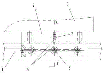
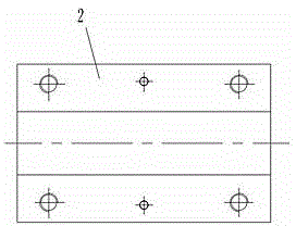
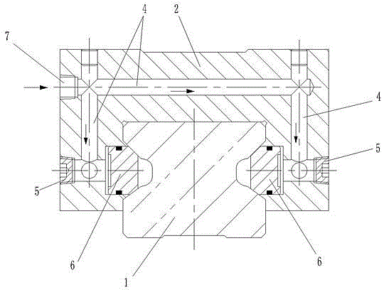
[0009] Such as figure 1 , 2 , 3 shows: 1 is two linear guide rails with grooves fixed on the bed, and the grooves on both sides of the guide rail 1 are V-shaped grooves. A sliding block 2 is provided with the guide rail 1. The sliding block 2 is fixed on the sliding table 3 by bolts, and the sliding block 2 and the sliding table 3 can slide relative to the guide rail 1. The sliding block 2 is matched with the upper surface of the guide rail 1, and the lower two sides of the sliding block 2 are located outside the two sides of the guide rail 1.

[0010] The slider 2 is processed with oil passages 4 connected to the hydraulic control device. A plurality of axially movable plungers 6 are arranged on the inner sides of the slider 2, and one end of the plunger 6 faces the groove on the side of the guide rail 1. It coincides with the inclined surface of the V-shaped groove, that is, the end surface of the plunger 6 has an inclined surface that coincides with the V-shaped groove. The o...


PUM


Abstract

A linear guide rail automatic clamping mechanism with grooves on two sides comprises a linear guide rail which is fixed on a machine and which is provided with the grooves on the two sides. A slider matches with the guide rail and is provided with oil ways connected with a hydraulic control device by machining, a plurality of plugs capable of axially moving are arrayed on the two inner sides of the slider, one end faces of the plugs face to the side of the guide rail and fit a V-shaped groove on the side of the guide rail, the other end faces of the plugs are communicated with the oil ways, and an oil inlet which is communicated with the oil ways and which is connected to the hydraulic control device through a joint and a pipeline is formed in the slider. When the slider moves in the right place, pressure oil is provided to the oil ways through the hydraulic control device, the plugs press onto the two side V-shaped faces of the guide rail, and clamping and locking are realized. Conversely, the oil pressure is relieved and the plugs float and release, so locking is released. The slider and the guide rail are positioned directly, other components are free of influence, a drive mechanism of the slider is individual, and the linear guide rail automatic clamping mechanism is stable, firm, sensitive and reliable.

Description

Technical field [0001] The invention relates to a holding mechanism, in particular to a linear guide automatic holding mechanism with grooves on both sides. Background technique [0002] The cooperation of linear guide rail and slider is one of the commonly used mechanical power components. For example, the machine bed is equipped with linear guide rail, the guide rail is equipped with a sliding block, and a sliding table is fixed above the sliding block. The sliding table and the sliding block are driven by the driving mechanism. Move relative to the rail. When the sliding table moves into position, the driving mechanism stops driving, so that the sliding table stops moving. In this way, there is no holding or locking mechanism between the sliding block and the guide rail, and the stopping of the sliding table and the sliding block only relies on the self-locking of the driving mechanism. The driving mechanism drives the sliding table and the sliding block to move through the ...

Claims


Application Information

Patent Timeline
IPC IPC(8): B23Q1/26B23Q1/38
CPCB23Q1/287
Inventor 杨曙光
Owner DALIAN HUAGEN MACHINERY
Why Eureka
Try Eureka