Rotary compact spinning fiber gathering device

A rotary, fiber bundling technology, applied in the field of fiber agglomeration device and spinning processing equipment, can solve the problems of decreased evenness evenness and insufficient agglomeration of fiber bundles, and achieves high evenness and low frictional resistance. , the effect of less hairiness

Inactive Publication Date: 2014-05-28
ZHEJIANG SCI-TECH UNIV
View PDF5 Cites 7 Cited by
  • Summary
  • Abstract
  • Description
  • Claims
  • Application Information

AI Technical Summary

Problems solved by technology

[0005] The above-mentioned mechanical compact spinning fiber gathering device and yarn processing method have the following disadvantages: (1) when the fiber whiskers are gathered in the fiber gathering channel, the frictional force and the fiber whiskers imparted by the fiber gathering channel to the fiber whiskers The transport direction is opposite, so

Method used


Image

  • Rotary compact spinning fiber gathering device
  • Rotary compact spinning fiber gathering device
  • Rotary compact spinning fiber gathering device

Examples


Embodiment 1

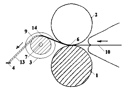
[0021] Such as image 3 , 4, in this embodiment, the rotary compact spinning fiber gathering device consists of a drafting roller 1, a drafting top roller 2, a fiber bundler 3, a yarn guide hook 4 and a support mechanism 8 fixedly installed The connecting shaft 5 is composed. The drafting roller 1 is tightly pressed on the drafting top roller 2 to form a drafting nip line 6 . The fiber bundler 3 is arranged downstream of the drafting nip line 6, so that the fiber bundler 3 forms a positive grid distance with the drafting roller 1 and the drafting top roller 2 respectively. The yarn guide hook 4 is arranged downstream of the fiber bundler 3 . A shaft hole 7 is opened on the fiber bundler 3, and one end of the connecting shaft 5 is installed in the shaft hole 7 through a rolling bearing, and the other end of the connecting shaft 5 is fixedly installed on the support mechanism 8, so that the fiber bundler 3 can Driven to rotate around the connecting shaft 5. There is an annul...

Embodiment 2

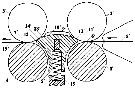
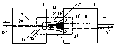
[0023] Such as Figure 5 , 6 As shown, in this embodiment, the rotary compact spinning fiber gathering device consists of a drafting roller 1, a drafting top roller 2, a fiber cluster 3, a yarn guide hook 4 and a connecting shaft fixedly installed on a supporting mechanism 8. 5 composition. The drafting roller 1 is tightly pressed on the drafting top roller 2 to form a drafting nip line 6 . The fiber bundler 3 is arranged downstream of the drafting jaw line 6 , and the yarn guide hook 4 is arranged downstream of the fiber bundler 3 . A shaft hole 7 is opened on the fiber bundler 3, one end of the connecting shaft 5 is installed in the shaft hole 7 through a rolling bearing, and the other end of the connecting shaft 5 is fixedly installed on the support mechanism 8, so that the fiber bundler 3 can be driven by an external force. Rotate around connecting axis 5. Different from Embodiment 1, in this embodiment, the drafting top roller 2 is tightly pressed on the fiber bundler...


PUM


Abstract

The invention discloses a rotary compact spinning fiber gathering device, which comprises a drawing roller, a drawing leather roller, a fiber buncher, a yarn guiding hook and a connecting shaft fixedly installed on one supporting mechanism, wherein the fiber buncher is provided with a shaft hole; the connecting shaft is installed in the shaft hole via a rolling bearing; the fiber buncher is provided with an annular slot by taking the shaft hole as the center; the width of the cross section of the annular slot is gradually reduced to the bottom direction from the opening; the drawing roller is tightly pressed on the drawing leather roller to form a drawing jaw line; the fiber buncher is arranged on the lower position of the drawing jaw line; the yarn guiding hook is arranged on the lower position of the fiber buncher; a fiber tassel clump output by the drawing jaw line can pass through the yarn guiding hook after passing through the annular slot. The rotary compact spinning fiber gathering device disclosed by the invention has the advantages that the fiber buncher can rotate, the bottom of the annular slot can be narrower, so that the fiber gathering effect is better. The processed yarn has high yarn levelness evenness and little and short hairiness.

Description

technical field [0001] The invention belongs to the field of textile processing, and relates to spinning processing equipment, in particular to a fiber gathering device used on a ring spinning frame. Background technique [0002] The mechanical compact spinning technology refers to the addition of a mechanical fiber accumulation device before the drafting front roller pair of the traditional ring spinning machine. The core area of ​​the fiber accumulation device is the fiber accumulation area. Lateral movement occurs in the fiber accumulation area, so that the fiber bundles of a certain width entering the fiber accumulation area through the nip line before drafting gradually become narrower, and the jaws are held by twisting under the condition that the fibers are arranged smoothly and tightly. The thread enters the twisting zone. [0003] Such as figure 1 , 2 As shown, the patent document CN1849421 of the Rieter company in Switzerland discloses a mechanical fiber gatheri...

Claims


Application Information

Patent Timeline
IPC IPC(8): D01H5/72
Inventor 王彩华
Owner ZHEJIANG SCI-TECH UNIV
Why Eureka
Try Eureka