Sensor

A technology for sensors and outer shells, applied in the field of sensors, which can solve the problems of transferring chemical characteristics to sensors, low precision, and slow response of sensors

Active Publication Date: 2014-05-28
厦门易感智能测控技术有限公司
View PDF9 Cites 17 Cited by
  • Summary
  • Abstract
  • Description
  • Claims
  • Application Information

AI Technical Summary

Problems solved by technology

[0002] The probes of existing sensors (mainly referring to temperature sensors and chemical analysis sensors) are simple geometric shapes such as cylinders or squares, and the amount of measurement medium in contact with them is small and th...

Method used


Image

  • Sensor
  • Sensor
  • Sensor

Examples


Embodiment 1

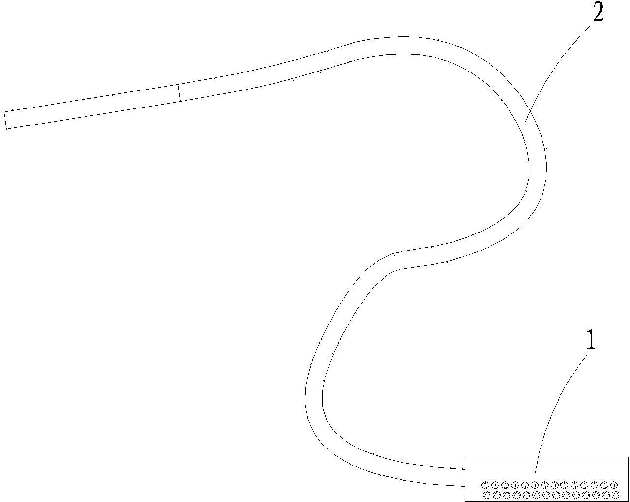
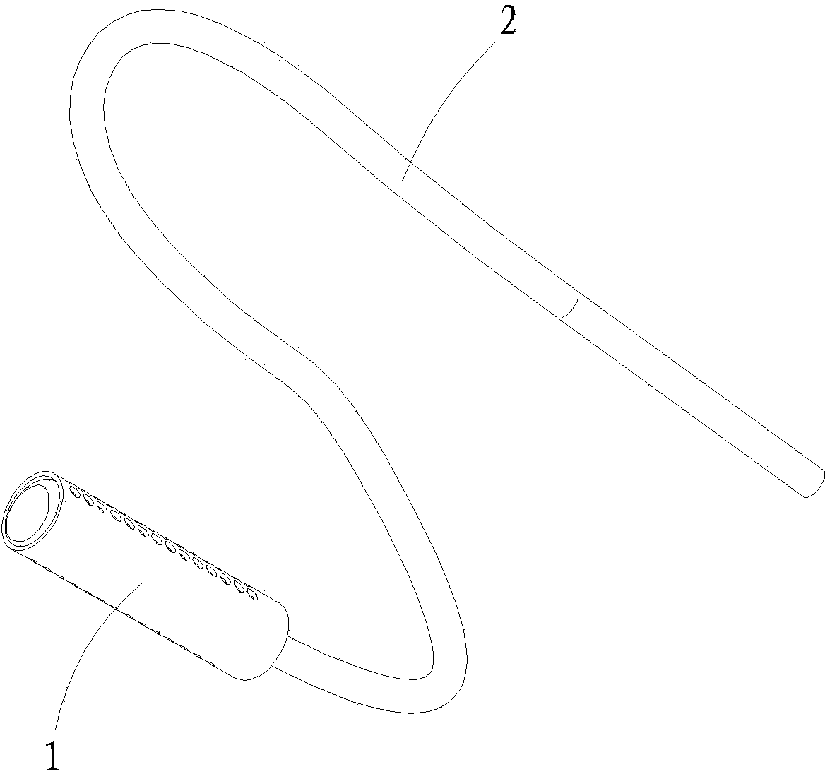
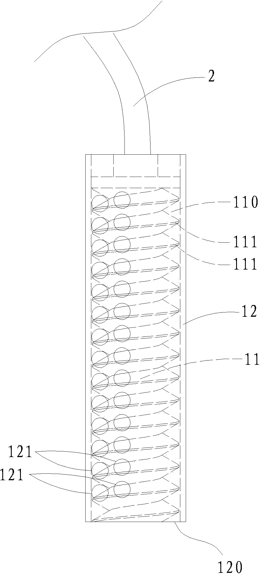
[0025] See Figure 1a , Figure 1b with figure 2 , image 3 As shown, the sensor of this embodiment includes a probe 1 for measurement and a cable 2 connected to the upper end of the probe 1. The probe 1 of the sensor includes an inner part 11 and an outer body 12 sleeved with the inner body 11, the inner part 11 is provided with a core of the sensor (not shown in the figure), and the surface of the inner part 11 has A section of spiral channel 110, the lower end of the outer shell 12 has an opening 120, so that the inner part 11 and the outer shell 12 sleeved with the inner body 11 form a hollow double-layer structure with a spiral channel and an open lower end; and The outer shell 12 is provided with a plurality of through holes 121 at positions corresponding to the inner spiral channel. Among them, in this embodiment, the multiple through holes 121 opened on the outer shell 12 are distributed on two straight lines (for ease of processing), and the distance between the holes ...

Embodiment 2

[0030] See Figure 4 with Figure 5 As shown, the second embodiment is basically the same as the first embodiment, the difference is: the through hole 121 opened on the outer shell 12 in the second embodiment is a square hole, while the outer shell 12 in the first embodiment is opened The through hole 121 is a round hole. Of course, the through holes 121 opened on the outer shell 12 in other embodiments may also be elliptical holes or through holes of other shapes.

[0031] In addition, the multiple through holes 121 formed on the outer shell 12 in the second embodiment can also be roughly distributed in a straight line, and for other changes, please refer to the above description of the first embodiment.

Embodiment 3

[0033] See Image 6 As shown, this embodiment 3 is different from the above-mentioned embodiment 1 and embodiment 2 in the way of opening a plurality of through holes 121 on the outer shell 12, instead of the elongated slot 122, and the rest is the same. By replacing the above-mentioned design of multiple through holes 121 arranged on one or more straight lines with elongated slots 122 on the outer shell 12, similar effects can basically be achieved, but the processing and manufacturing are more Convenient.

[0034] In order to explain in more detail that the sensor of the present invention does have technical advantages compared to the prior art, the following further expands the description with the measurement application method of Embodiment 1.

[0035] See Figure 7 with Picture 8 As shown, embodiment 1 is installed and placed in a pipe 3 for measurement. When the probe 1 of Embodiment 1 is installed and placed, the outer shell 12 of the probe 1 is provided with a through h...


PUM


Abstract

The invention relates to a sensor, and particularly relates to a structure improvement of a sensor, with which various fluid media can be fully in contact with a measurement probe. A probe of the sensor disclosed by the invention comprises an internal element and an outer shell with which the internal element is sleeved, wherein the internal element is internally provided with a chip body; the surface of the internal element is provided with a spiral channel; the lower end of the outer shell is provided with an opening, so that the internal element and the outer shell with which the internal element is sleeved form a hollow dual-layer structure which is provided with the spiral channel and is open at the lower end; a plurality of through holes are formed in the outer shell and correspond to the internal spiral channel. The sensor provided by the invention is used for performing sensing measurement on a fluid.

Description

Technical field [0001] The invention relates to a sensor, in particular to the improvement of the structure of the sensor capable of fully contacting the measuring probe with various fluid media. Background technique [0002] Existing sensors (mainly temperature sensors, chemical analysis sensors) probes are simple cylindrical or square and other geometric shapes, the amount of measurement medium in contact with them is small, and the contact surface is insufficient; therefore, the structure of the existing sensors has slow response and poor accuracy. High, the measured medium cannot transmit relevant physical and chemical characteristics to the technical deficiencies of the sensor. Summary of the invention [0003] Therefore, in order to solve the shortcomings of the prior art, the present invention proposes a sensor that enables various fluid media to fully contact the measuring probe. [0004] The present invention specifically adopts the following technical solutions to achieve...

Claims


Application Information

Patent Timeline
IPC IPC(8): G01D5/12
Inventor 何雪松
Owner 厦门易感智能测控技术有限公司
Why Eureka
Try Eureka