Rapid m-sequence capture method for signal simulation
A signal simulation, m-sequence technology, applied in the field of signal simulation, can solve the problem of long acquisition time, and achieve the effect of shortening the acquisition period and fast acquisition
- Summary
- Abstract
- Description
- Claims
- Application Information
AI Technical Summary
Problems solved by technology
Method used
Image

Examples
specific Embodiment approach 1
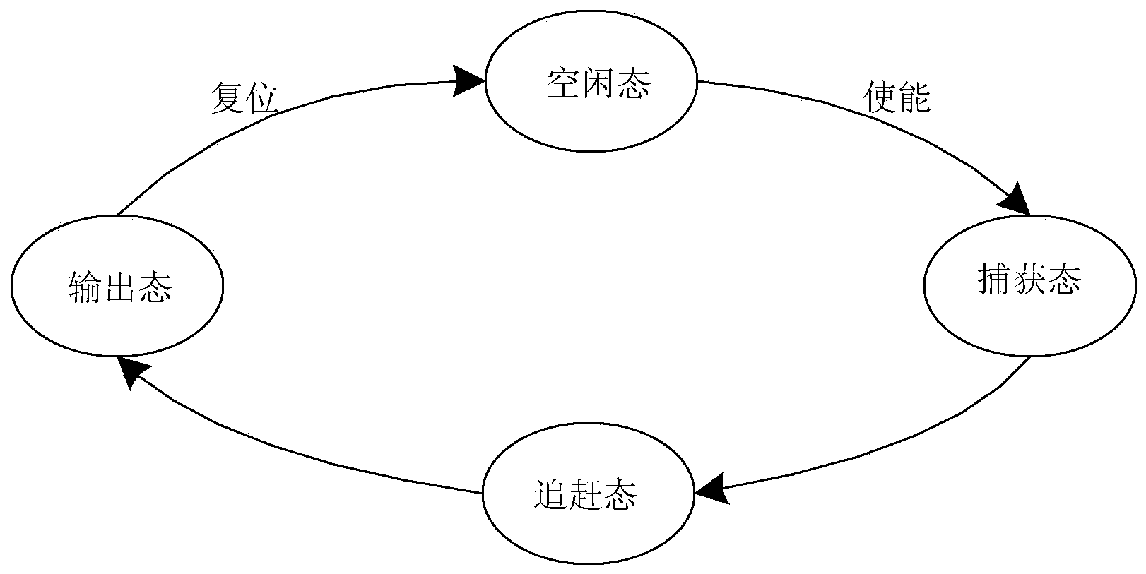
[0028] Specific implementation mode one: the following combination Figure 1 to Figure 5 Describe this embodiment, the fast m-sequence capture method for signal simulation described in this embodiment, it includes three steps of capture of target signal m-sequence, catching up of target signal m-sequence and synchronous output of target signal m-sequence, specifically :
[0029] Step 1: Using the same clock pulse as the target signal, the n-level state value of the m-sequence of the target signal within n clock cycles is captured by the signal simulator, and the n-level state value is synchronized as the n-level m-sequence in the signal simulator The initial input value of the n-stage shift register of the generator;
[0030] Step 2: Starting from the n+1th clock cycle, obtain the state value of the target signal in the subsequent clock cycle according to the n-level state value of the target signal in m sequence within n clock cycles and its characteristic polynomial f(x) si...
specific Embodiment approach 2
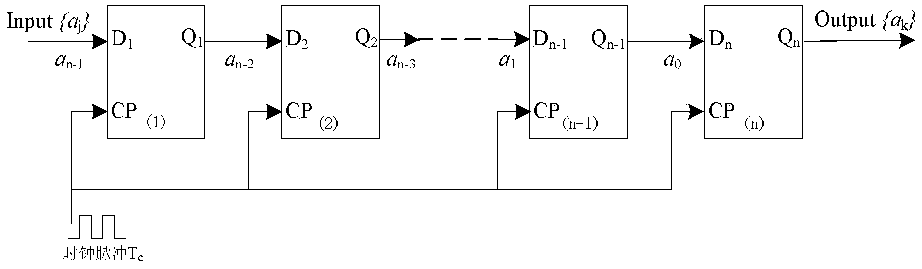
[0033] Specific implementation mode two: the following combination figure 1 and figure 2 This embodiment will be described. This embodiment will further describe the first embodiment. In this embodiment, in step one, the n-level state values of the m sequence of the target signal within n clock cycles are sequentially expressed as a 0 ,a 1 ,a 2 ,...a n-1 , and the clock pulse of the target signal is denoted as T c .
[0034] In this embodiment, it is assumed that starting from time 0, the signal simulator captures n-level state values of m sequences within n periods of the target signal, which are respectively denoted as a 0 ,a 1 ,a 2 ,...a n-1 , and in turn as the n-stage shift register input. After n shift pulses T c The outputs of the shift registers of the subsequent stages are as follows figure 2 shown. The purpose of this step is to obtain the n-level state value of the target m-sequence as the initial value of the simulated m-sequence, and this proces...
specific Embodiment approach 3
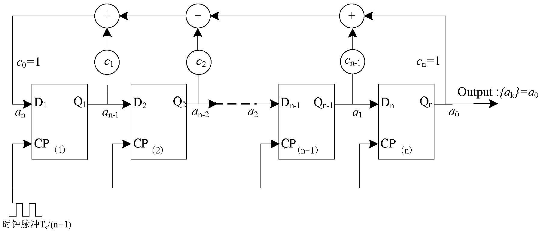
[0035] Specific implementation mode three: the following combination Figure 1 to Figure 5 Describe this embodiment, this embodiment will further explain the second embodiment, this embodiment is: in step two, the acceleration clock pulse T is:
[0036] T=T c / (n+1).
[0037] In step 2, use the acceleration clock T=T c / (n+1), that is, in a T cn+1 shift operations are completed within a period of time. Among them, the start state and end state of the m-sequence catch-up process are as follows: image 3 and Figure 4 shown. By speeding up the clock by a factor of n+1, it is achieved at (n+1)T c At time, the m-sequence value of the analog output is exactly the n+1th value of the target m-sequence output. At this time, the m-sequence generator has caught up with the target in terms of elapsed time and output value.
[0038] In step 3, the synchronous output with the target signal is realized. In step 2, after catching up with the clock of the target m-sequence generator,...
PUM
 Abstract
Description
Claims
Application Information
 - Generate Ideas
- Intellectual Property
- Life Sciences
- Materials
- Tech Scout
- Unparalleled Data Quality
- Higher Quality Content
- 60% Fewer Hallucinations
Browse by: Latest US Patents, China's latest patents, Technical Efficacy Thesaurus, Application Domain, Technology Topic, Popular Technical Reports.
© 2025 PatSnap. All rights reserved.Legal|Privacy policy|Modern Slavery Act Transparency Statement|Sitemap|About US| Contact US: help@patsnap.com