Eureka AIR delivers breakthrough ideas for toughest innovation challenges, trusted by R&D personnel around the world.

variable capacitor generator

A technology of variable capacitors and generators, applied in the direction of induction generators, etc., can solve the problems of small power/weight ratio, low conversion efficiency, and large consumption, and achieve high power/weight ratio, less use, and low calorific value Effect

Inactive Publication Date: 2016-05-11
HARBIN XIANGKAI TECH DEV
View PDF4 Cites 0 Cited by
  • Summary
  • Abstract
  • Description
  • Claims
  • Application Information

AI Technical Summary

Problems solved by technology

[0003] The purpose of the present invention is to provide a variable capacitance generator. The present invention is to overcome the problems of low power / weight ratio, large amount of copper consumption, low conversion efficiency and large calorific value in existing electromagnetic generators.

Method used


Image

  • variable capacitor generator
  • variable capacitor generator
  • variable capacitor generator

Examples


specific Embodiment approach 1

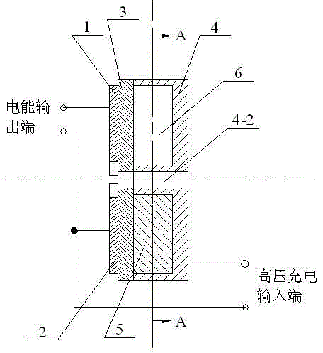
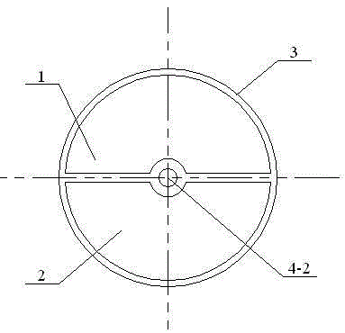
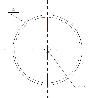
[0008] Specific implementation mode one: combine figure 1 , figure 2 , image 3 , Figure 4 , Figure 5 , Image 6 Describe this embodiment, this embodiment consists of a first semicircular conductive metal sheet 1, a second semicircular conductive metal sheet 2, a dielectric disc 3, a circular iron tank 4, a conductive liquid 5, and an inert gas 6;

[0009] An end face of the first semicircle conductive metal sheet 1 and an end face of the second semicircle conductive metal sheet 2 are all connected with an end face of the dielectric disc 3, and the first semicircle conductive metal sheet 1 is opposite to the second semicircle conductive metal sheet 2 to form a The circular iron grooves are insulated from each other; the circular iron grooves 4 are sheet-shaped cylinders with a rotating shaft hole 4-2, and an annular groove 4-1 is opened on the left end surface of the circular iron grooves 4; The other end surface of the dielectric disc 3 is sealed and connected to the ...


PUM


Abstract

The invention discloses a variable capacitive generator and relates to the technical field of conversion from mechanical energy into electric energy, for overcoming the problems of small power / weight ratio, large copper material consumption, low conversion usefulness, and high heat productivity of a conventional electromagnetic generator. In the variable capacitive generator, one end surface of a first semicircular conductive metal sheet and one end surface of a second semicircular conductive metal sheet are connected with one end surface of a dielectric wafer; the left side end surface of a circular ferruginous groove is provided with an annular groove; the other end surface of the dielectric wafer is in sealing connection with the left side end surface of the circular ferruginous groove to enable the annular groove on the left side end surface of the circular ferruginous groove to be completely sealed relative to the outside; and a conductive liquid and an inert gas are filled into the annular groove, and the volume of the conductive liquid is half of the space volume of the annular groove. The efficiency of the variable capacitive generator in converting the mechanical energy into the electric energy is more than 95%, the use amount of metal materials with good conductivity is small, the power / weight ratio is large, and the heat productivity is low.

Description

technical field [0001] The invention relates to the technical field of converting mechanical energy into electrical energy. Background technique [0002] The existing means of converting mechanical energy into electrical energy is the electromagnetic generator, which is widely used in various fields and has become an indispensable technological facility in people's life and production. However, there are still many problems in the existing generator, such as power The / weight ratio is small, a large amount of copper is consumed, the conversion efficiency is low, and the heat generation is large; a large amount of energy is consumed in the manufacturing process, and a large amount of energy is wasted in the power generation process. Contents of the invention [0003] The purpose of the present invention is to provide a variable capacitance generator. The present invention aims to overcome the problems of low power / weight ratio, large copper consumption, low conversion effic...

Claims


Application Information

Patent Timeline
Patent Type & Authority Patents(China)
IPC IPC(8): H02N1/08
Inventor 雷涛
Owner HARBIN XIANGKAI TECH DEV
Why Eureka
Eureka Blog
Learn More