Optimized torsion box for an aircraft

一种航行器、抗扭箱的技术,应用在机身框架、弦杆/纵梁、胶粘剂等方向,能够解决成本高、抗扭箱成本高、高复杂性等问题

Active Publication Date: 2014-06-04
AIRBUS OPERATIONS SL
View PDF7 Cites 3 Cited by
  • Summary
  • Abstract
  • Description
  • Claims
  • Application Information

AI Technical Summary

Problems solved by technology

The torsion box manufactured using the described method is expensive because the steps will be performed individually for each structural element
Furthermore, the costs associated with the assembly of the torsion boxes are high due to the long length and the high complexity of the tasks required to install and fit together all the structural elements

Method used


Image

  • Optimized torsion box for an aircraft
  • Optimized torsion box for an aircraft
  • Optimized torsion box for an aircraft

Examples


Embodiment Construction

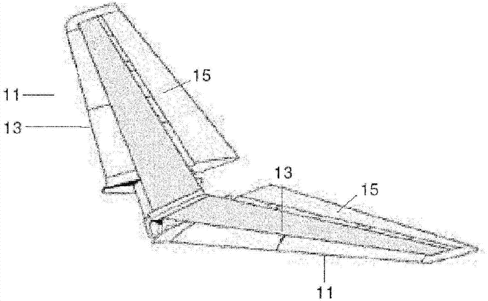
[0035] In the following detailed description we will refer to the torsion box of the HTP, but the invention is applicable to the torsion box of any lifting surface of an aircraft.

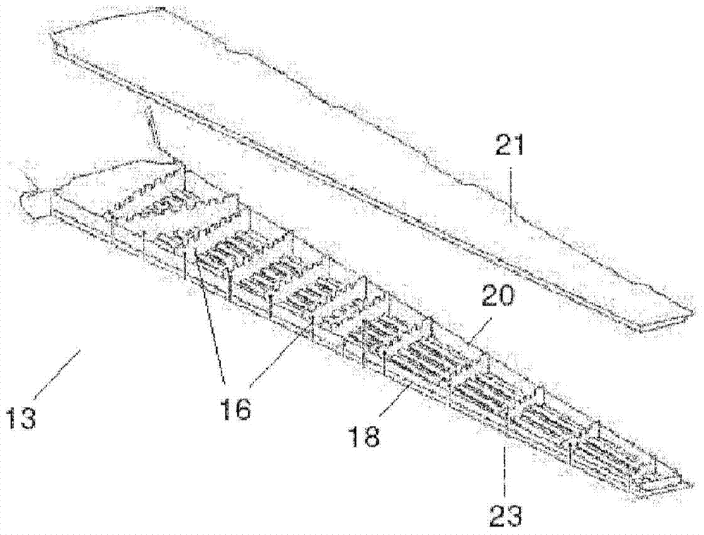
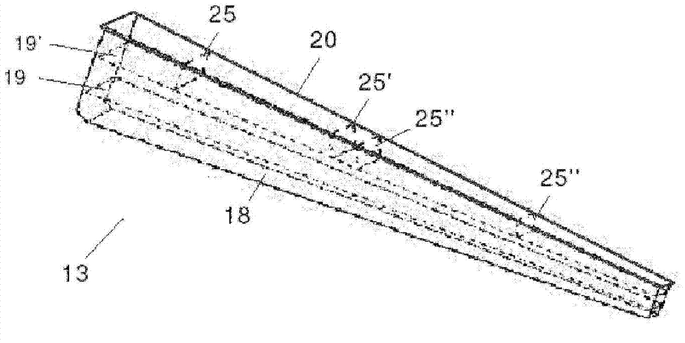
[0036] Figure 2a A composite torsion box 13 of HTP according to an embodiment of the present invention is shown, comprising the following structural elements:

[0037] - The front spar 18, the rear spar 20 and the intermediate spars 19, 19'.

[0038] - Upper skin 21 and lower skin 23 .

[0039] - Several transverse ribs 25, 25', 25", 25'" between the rear spar 20 and its adjacent middle spar 19'.

[0040] This arrangement, which is very advantageous from a manufacturing point of view, solves the particular loading problem at the rear of the torsion box that occurs in many typical HTP architectures.

[0041] In this sense the transverse rib 25 is arranged to receive and distribute the load from the pivot point of the axis of rotation of the HTP and the ribs 25', 25" are arranged to receive and d...


PUM


Abstract

The invention provides an aircraft lifting surface with a torsion box (13) of a composite material comprising an upper skin (21), a lower skin (23), a front spar (18), a rear spar (20), one or more intermediate spars (19, 19') and a plurality of transverse ribs (25, 25', ...) arranged between the rear spar (20) and its adjacent intermediate spar (19') and / or between the front spar (18) and the adjacent intermediate spar (19) for improving its structural behavior. The invention also provides a manufacturing method of said torsion box.

Description

technical field [0001] The invention relates to a torsion box of an aircraft, in particular to a torsion box of a lifting surface. Background technique [0002] The structure of an aircraft's lifting surface usually includes a torsion box. For example, an aircraft empennage (horizontal or vertical) is usually constructed from a leading edge, a torsion box and a trailing edge with control surfaces (flaps, elevator, rudder, etc.). [0003] The torsion box is the main structure responsible for supporting all the loads involved (aerodynamic, fuel, dynamic, etc.) and consists of several structural elements. [0004] Composites with an organic matrix and continuous fibers, especially carbon fiber reinforced plastics (CFRP), are today widely used in the aerospace industry in a wide variety of structural elements. In particular, all elements that make up the torsion boxes of aircraft empennages and other lifting surfaces can be manufactured using carbon fiber composites. [0005]...

Claims


Application Information

Patent Timeline
Patent Type & Authority Applications(China)
IPC IPC(8): B64C1/06
CPCB64C3/185B64C3/187B64C3/18Y10T156/10
Inventor E·季纳尔多弗纳恩德兹弗朗西斯科·何塞·克鲁兹多明古埃斯弗兰西斯科·哈维尔·奥诺雷托鲁伊斯保拉·马斯马斯伊凯尔·贝莱斯德门迪萨瓦尔阿朗索卡洛斯·加西亚涅托
Owner AIRBUS OPERATIONS SL
Why Eureka
Try Eureka