Method used for power transmission system possessing transmission and clutch

A technology for power transmission systems, transmissions, applied in transmissions, elements with teeth, transmission control, etc., can solve problems such as unacceptable, inaccurate, excessive fuel consumption, etc.

Active Publication Date: 2014-06-04
FORD GLOBAL TECH LLC
View PDF7 Cites 7 Cited by
  • Summary
  • Abstract
  • Description
  • Claims
  • Application Information

AI Technical Summary

Problems solved by technology

As such, these tables may be inaccurate, resulting in

Method used


Image

  • Method used for power transmission system possessing transmission and clutch
  • Method used for power transmission system possessing transmission and clutch
  • Method used for power transmission system possessing transmission and clutch

Examples


Embodiment Construction

[0031] Specific embodiments of the present invention are disclosed herein; however, it is to be understood that the disclosed embodiments are merely exemplary of the invention, which may be embodied in various and alternative forms. The figures are not necessarily to scale; some features may be exaggerated or minimized to show details of particular components. Therefore, specific structural and functional details disclosed herein are not to be interpreted as limiting, but merely as a representative basis for teaching one skilled in the art to variously employ the present invention.

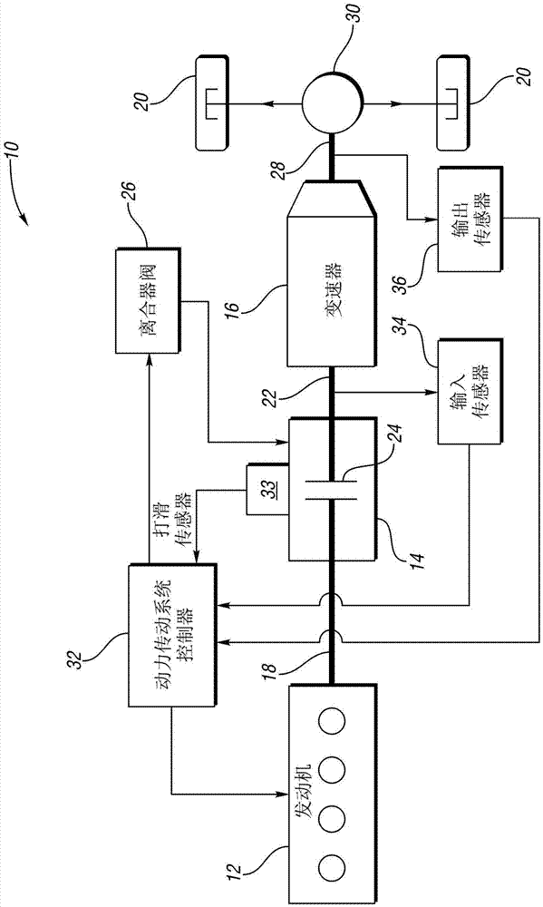
[0032] now refer to figure 1 , shows a block diagram of an exemplary powertrain 10 for a vehicle according to an embodiment of the present invention. The powertrain 10 includes an engine 12 , a torque converter 14 and a multi-speed automatic transmission 16 . An output shaft 18 of the engine 12 is connected to the upstream side of the torque converter 14 . The upstream side of the transmission ...


PUM


Abstract

Provided is a method used for a power transmission system possessing a transmission and clutch. The power transmission system is used for a vehicle. The slip of the clutch is adjusted to a target where a magnitude of a sensed parameter of a shaft of the transmission corresponds to a desired noise, vibration, and harshness (NVH) level in the power transmission system. The sensed parameter of the transmission shaft may be one of acceleration, speed, and torque of the transmission shaft. The transmission shaft may be one of the input shaft and output shaft of the transmission.

Description

technical field [0001] The present invention relates to regulating clutch slip upstream of a transmission to control noise, vibration and harshness (NVH) effects in a vehicle powertrain. Background technique [0002] A vehicle powertrain includes an engine and a transmission, wherein torque (or power) generated by the engine is transmitted to drive wheels through the transmission. In some drivetrains, the engine is connected to the transmission via a clutch such as a bypass clutch on a torque converter with which the transmission is equipped, or an input clutch on a dual clutch transmission or a mechanical automatic transmission. Here, the bypass clutch on the torque converter will be used to indicate any clutch type. [0003] Slipping of the bypass clutch indicates how engaged the torque converter is. Operation of the bypass clutch at high slip provides greater hydraulic coupling between the engine and transmission, which suppresses driveline disturbances due to torque di...

Claims


Application Information

Patent Timeline
IPC IPC(8): F16H61/14
CPCB60W10/02F16H61/14F16H2061/147F16H2061/145B60W10/026B60W30/18B60W2510/0241B60W10/11
Inventor 格雷戈里·迈克尔·皮尔准恩藤井雄二黛安娜·雅娜奇维夫约瑟夫·F·库哈尔斯基尼姆罗德·卡帕斯亚历山大·奥康纳·吉布森李承勋
Owner FORD GLOBAL TECH LLC
Why Eureka
Try Eureka