Rod displacement sensor angular measurement clamp

A displacement sensor and angle measurement technology, which is applied in angle/taper measurement and other directions, can solve the problems of measurement result limitations, errors, accurate measurement sensors, etc., and achieve the effect of convenient and detailed grasp, elimination of safety hazards, and improvement of precision

Active Publication Date: 2014-06-04
SHENYANG AIRCRAFT CORP
View PDF8 Cites 6 Cited by
  • Summary
  • Abstract
  • Description
  • Claims
  • Application Information

AI Technical Summary

Problems solved by technology

In the aircraft control system test, in order to ensure the accurate data required for the test, it is necessary to obtain the rotation angle of the pointer of the rod displacement sensor many times, and effectively record and analyze the test data corresponding to each angle, so as to obtain the corresponding value of the rotation angle of the sensor pointer. Test-related data, but on the rod displacement sensor, the angle dial is in units of 5°, which cannot comprehensively and accurately measure the rotation angle of the sensor. There are limitations and large errors in the measurement results, which directly affect the comprehensiveness of the test conclusion and accuracy, resulting in the inability to comprehensively and accurately grasp the performance indicators of the aircraft, leaving hidden dangers to flight safety
In addition, due to the special structure of the rod displacement sensor, it cannot be measured with a traditional angle ruler

Method used


Image

  • Rod displacement sensor angular measurement clamp
  • Rod displacement sensor angular measurement clamp
  • Rod displacement sensor angular measurement clamp

Examples


Embodiment Construction

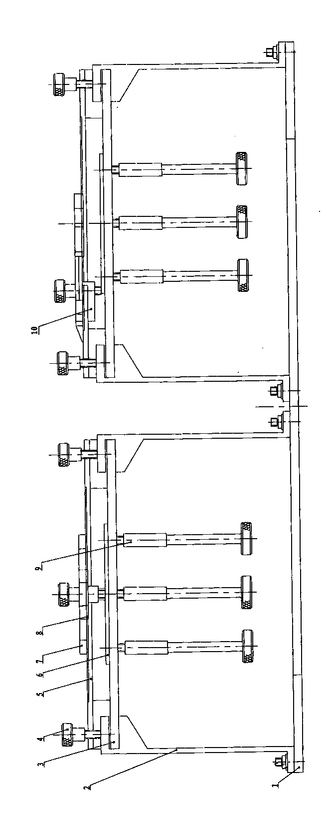
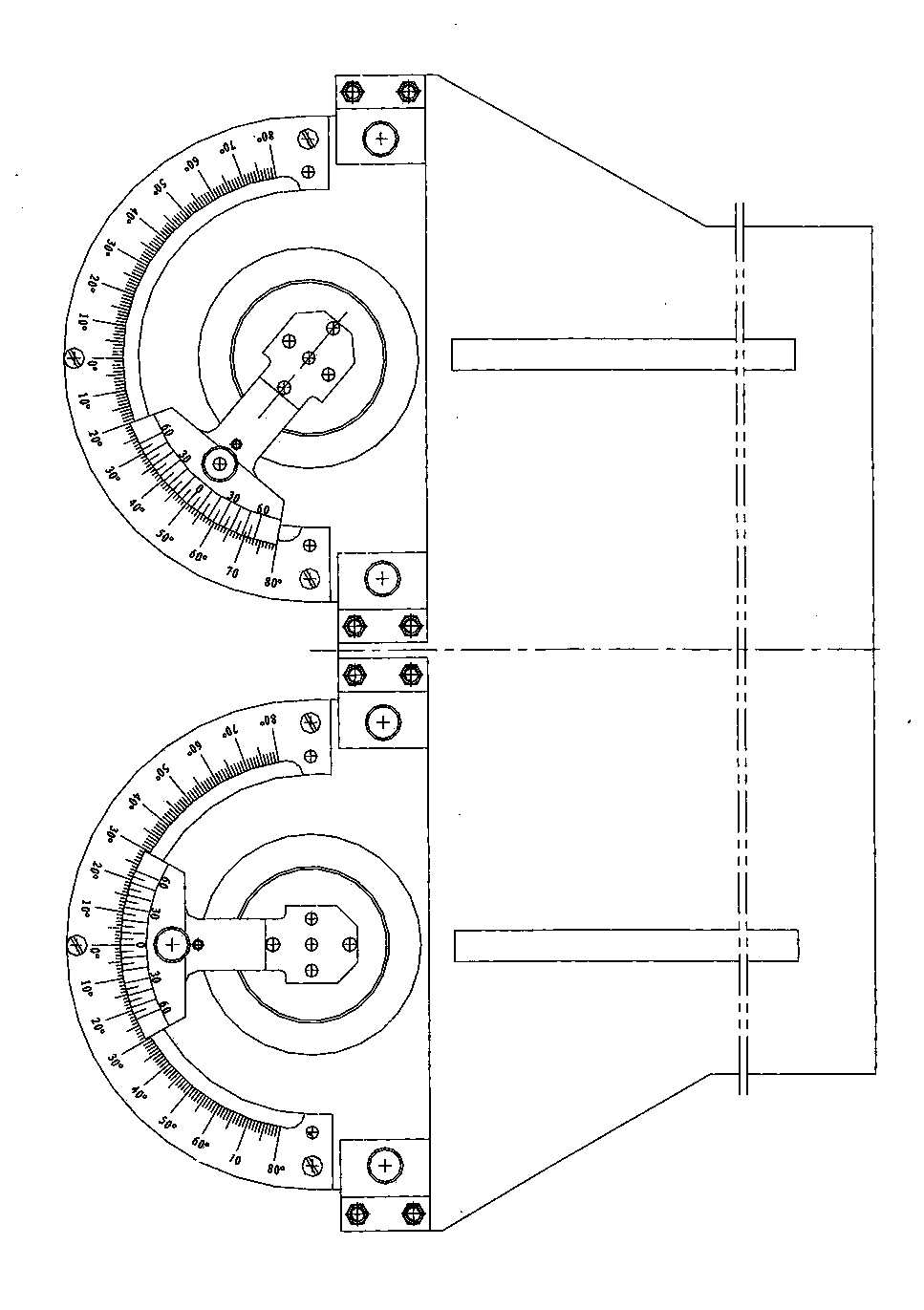
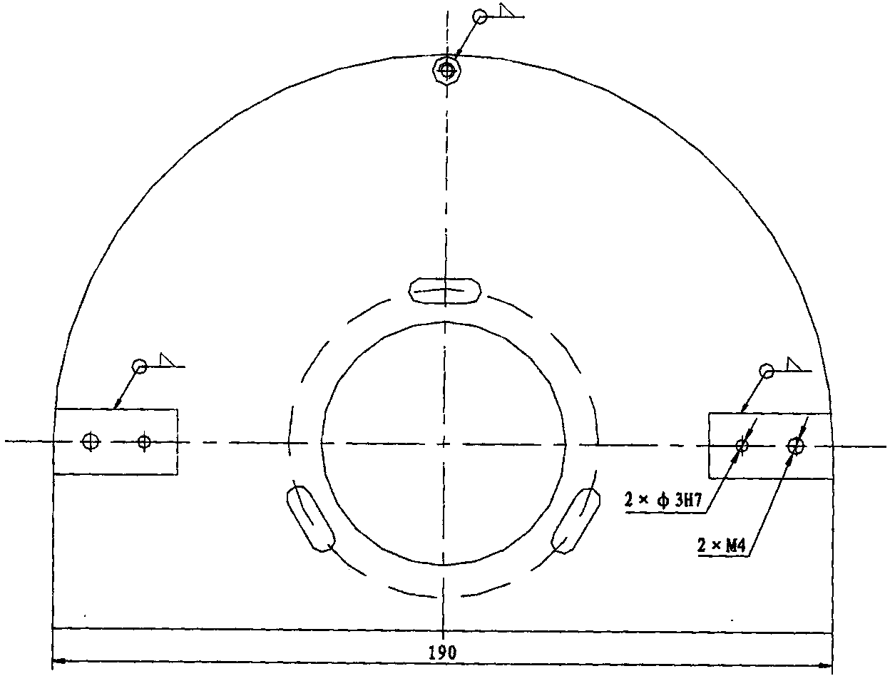
[0014] Such as figure 1 with figure 2 As shown, the rod displacement sensor angle measurement fixture, the support plate 3 is horizontally fixed on the frame body composed of the bracket 2 and the bottom plate 1 through the screw 4, a round hole is opened in the middle of the support plate 3, and the size of the round hole is the same as the circle of the rod displacement sensor. The size of the shaped boss is the same, and there are three slots evenly distributed around the round hole, the position of the slots is in harmony with the three threaded holes on the rod displacement sensor, and the dial 5 is fixedly connected to the top of the support plate 3 by bolts, The center of circle of the dial 5 coincides with the center of circle on the support plate 3, and a three-claw washer 6 is arranged between the dial 5 and the support plate 3, such as Figure 5 As shown, the three-jaw washer 6 is formed by vertically welding three bolts 6-1 on the washer 6-2, the washer 6-2 is at...


PUM


Abstract

The invention provides a rod displacement sensor angular measurement clamp. A supporting plate is fixed to a frame body through screws, the frame body is composed of a support and a base plate, a round hole is formed in the middle of the supporting plate, three groove holes are evenly distributed in the periphery of the round hole, the positions of the groove holes are coordinated and consistent with three threaded holes in a rod displacement sensor, an index dial is fixedly connected with the upper portion of the supporting plate through bolts, a three-jaw gasket is arranged between the index dial and the supporting plate, three bolts of the three-jaw gasket fall into the three groove holes in the supporting plate respectively and are matched and connected with three long nuts, the rod displacement sensor is fixed to the supporting plate through the bolts and the long nuts, a circular boss on the upper end portion of the rod displacement sensor penetrates out of the middle round hole of the supporting plate and then is fixedly connected with a vernier through bolts, the vernier is used in cooperation with the index dial, and the position of the vernier and the position of the index dial are relatively fixed through a fastener. The rod displacement sensor angular measurement clamp solves the problem that the rotating angle of a rod displacement sensor pointer cannot be measured comprehensively and precisely.

Description

technical field [0001] The invention relates to a fixture for measuring the angle of a rod displacement sensor, which is used for precisely controlling the rotation angle of the pointer of the rod displacement sensor. Background technique [0002] Rod displacement sensor is a kind of angle measurement sensor commonly used in the technical field of aircraft, and the circular boss and pointer at the upper end of it play an indicating role. In the aircraft control system test, in order to ensure the accurate data required for the test, it is necessary to obtain the rotation angle of the pointer of the rod displacement sensor many times, and effectively record and analyze the test data corresponding to each angle, so as to obtain the corresponding value of the rotation angle of the sensor pointer. Test-related data, but on the rod displacement sensor, the angle dial is in units of 5°, which cannot comprehensively and accurately measure the rotation angle of the sensor. Ther...

Claims


Application Information

Patent Timeline
Patent Type & Authority Applications(China)
IPC IPC(8): G01B5/24
Inventor 李钢鸣张秀云孙承亮
Owner SHENYANG AIRCRAFT CORP
Why Eureka
Try Eureka