Finger vein recognition device and implement method thereof

A finger vein and recognition device technology, applied in character and pattern recognition, instruments, computer parts, etc., can solve the problems of high power consumption, identification, inconvenience, etc., to shorten the service life, improve consistency, and reduce authenticity rate effect

Active Publication Date: 2014-06-04
GUANGZHOU WEDONETECH TECH CO LTD
View PDF4 Cites 20 Cited by
  • Summary
  • Abstract
  • Description
  • Claims
  • Application Information

AI Technical Summary

Problems solved by technology

[0006] 1. The infrared light source, camera module, comparison module and other components of the existing finger vein recognition device are usually in the power-on or standby state all the time, and cannot enter the dormant state. The power consumption is high, and the long-term power-on shortens the service life of components;
[0007] 2. The camera module and the infrared light source are located above and below the guide groove respectively, blocking the user's sight, making it impossible for the user to see the position of the guide groove intuitively, standardizing the finger position, and affecting the user experience;
[0008] 3. Only through vein image recognition and comparison, but does not identify whether the finger is a living finger, making forged fingers a security risk;
[0009] 4. In order to meet the needs of most users, the existing guide groove is usually made relatively wide, so that even when the user's finger is placed in the guide groove, there is still a large room for movement. If the user's finger is placed too far, it is easy to cause identification Unsuccessful and other issues require the user to repeatedly adjust the finger position, which is inconvenient

Method used


Image

  • Finger vein recognition device and implement method thereof
  • Finger vein recognition device and implement method thereof
  • Finger vein recognition device and implement method thereof

Examples


Embodiment Construction

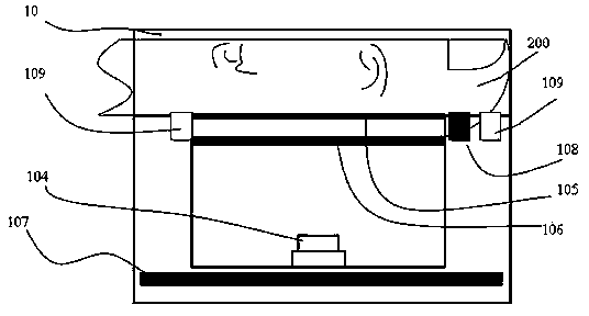
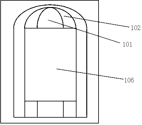
[0052] Such as figure 1 , figure 2 and image 3 As shown, a finger vein identification device, it includes a guide groove 10 for limiting the position of the finger to be measured, an infrared light source for illuminating the finger 200 on the guide groove 10, a camera module 104 for collecting finger vein images, and A comparison module for identifying the collected finger vein images, which also includes:

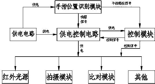
[0053] A power supply circuit and a power supply control circuit for controlling power supply;

[0054] A finger position recognition module, connected with the power supply circuit, used to sense the placement action of the finger on the guide groove 10;

[0055] A control module 107 is connected with the infrared light source, the photographing module 104 and the comparison module, and is powered by the power supply circuit through the power supply control circuit 107;

[0056] The finger vein recognition device includes at least one sleep state or deep sleep stat...


PUM


Abstract

The invention relates to a finger vein recognition device and an implement method thereof. The finger vein recognition device comprises a guide groove, an infrared light source, a shooting module, a comparison module, a power supply circuit, a power supply control circuit, a finger position recognition module and a control module, wherein the power supply control circuit performs power supply control on the power supply circuit; the finger position recognition module is connected with the power supply circuit and used for sensing placing action of the finger in the guide groove; the control module is connected with the infrared light source, the shooting module and the comparison module, and the power supply circuit supplies power to the control module through the power supply control circuit. The finger vein recognition device includes at least either a dormant state or a deep dormant state. The control module controls the infrared light source, the shooting module and the comparison module which are woken by power on to work and acquires and recognizes a vein image of the finger in the guide groove. The implement method is used for implementing the finger vein recognition device. The finger vein recognition device is simple in structure and capable of saving energy and electricity.

Description

[0001] Technical field: [0002] The invention relates to the technical field of finger vein recognition, in particular to a finger vein recognition device and an implementation method thereof. [0003] Background technique: [0004] With the intelligentization of identity recognition, fingerprint recognition and finger vein recognition are more and more favored by the majority of users. Finger vein recognition has gradually become more and more popular among users due to its advantages of high security, good confidentiality, fast recognition speed, non-contact, and high precision. As a reliable identification method, vein identification equipment will also become the preferred equipment for future identification. [0005] However, existing finger vein recognition devices have the following disadvantages: [0006] 1. The infrared light source, camera module, comparison module and other components of the existing finger vein recognition device are usually in the power-on or...

Claims


Application Information

Patent Timeline
Patent Type & Authority Applications(China)
IPC IPC(8): G06K9/00G06K9/20
Inventor 不公告发明人
Owner GUANGZHOU WEDONETECH TECH CO LTD
Why Eureka
Try Eureka