Light-emitting keyboard

A technology of luminous keyboards and luminous components, applied to electrical components, electrical switches, circuits, etc., can solve problems such as loss, uneven light distribution, and brightness impact

Inactive Publication Date: 2014-06-04
PRIMAX ELECTRONICS LTD
View PDF5 Cites 5 Cited by
  • Summary
  • Abstract
  • Description
  • Claims
  • Application Information

AI Technical Summary

Problems solved by technology

[0014] Firstly, the existing luminous keyboard 2 requires the bottom plate 23 to support the fixed lifting support device 212, and the light guide plate 241 is required to transmit light, which will increase the overall thickness of the luminous keyboard 2. Furthermore, the light transmitted in the light guide plate 241 is projected upwards to When the keycap 211 is used, it will first be partially lost or change the projection direction due to the influence of the circuit in the membrane switch circuit 22, and then it will be partially lost or change the projection direction due to the influence of the lifting support device 212 or the elastic member 213, so it is finally projected to The light of the keycap 211 will be unevenly distributed, and the brightness will also be affected
[0015] In addition, the elastic member 213 of the existing luminous keyboard 2 is mainly used to touch the membrane switch circuit 22, so that the upper contact point 221a contacts the lower contact point 222a, so the elastic member 213 must have a protruding portion 213a inside, and the shape of the elastic member 213 is determined. Restricted and cannot be changed arbitrarily, but such a shape tends to cause light to project in directions other than the keycap 211, which seriously affects the brightness of the keycap 211

Method used


Image

  • Light-emitting keyboard
  • Light-emitting keyboard
  • Light-emitting keyboard

Examples


Embodiment Construction

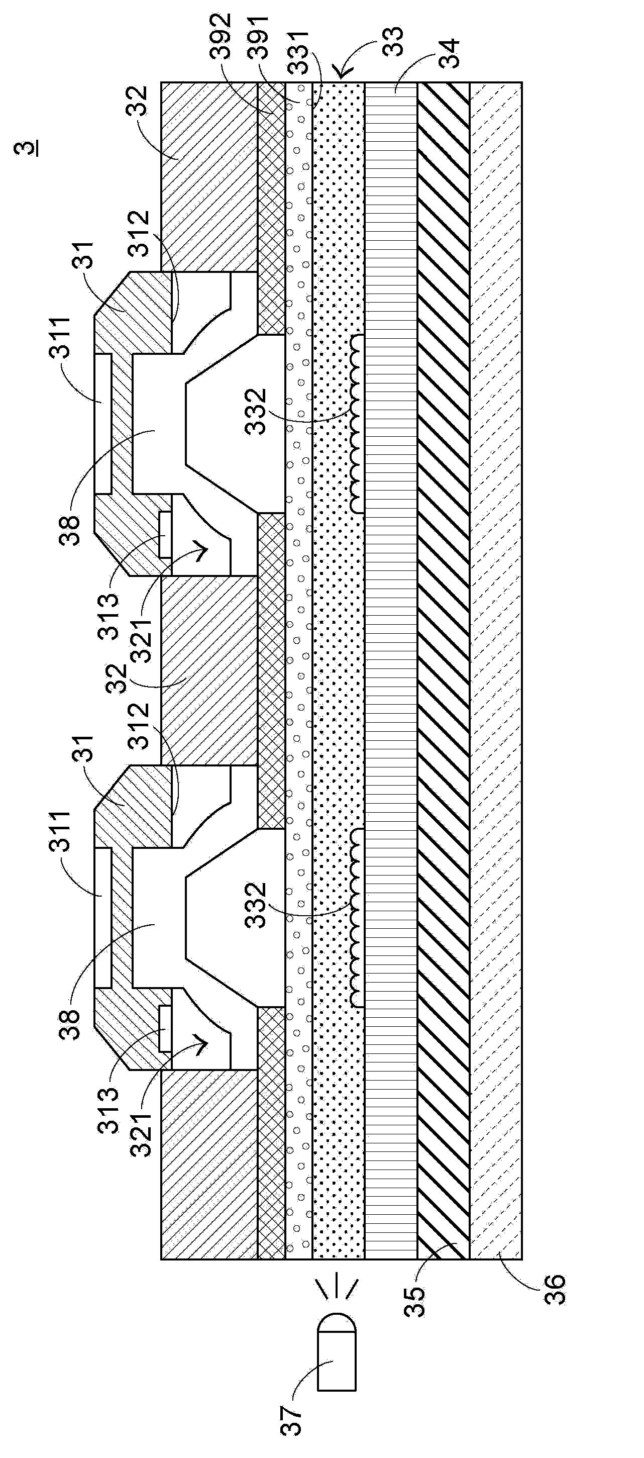
[0084] The luminous keyboard of a first preferred embodiment of the present invention is described below. see Figure 3A as well as Figure 3B , Figure 3A A first cross-sectional schematic diagram showing a light-emitting keyboard according to a first preferred embodiment of the present invention, Figure 3B A second cross-sectional schematic diagram showing a light-emitting keyboard according to a first preferred embodiment of the present invention.

[0085] The luminous keyboard 3 includes a keycap 31 , a keycap guide bracket 32 ​​, a light guide plate 33 , a reflective sheet 34 , an induction circuit layer 35 and a metal bottom plate 36 arranged in order from top to bottom. In addition, the light emitting element 37 is disposed on the side of the light guide plate 33 and the elastic element 38 is disposed between the keycap 31 and the light guide plate 33 .

[0086] The structure of each element of the luminous keyboard 3 and the relationship between these elements wil...


PUM


Abstract

The invention discloses a light-emitting keyboard comprising key caps, key cap guiding brackets, a light guide plate and an induction circuit layer which are arranged from the top to the bottom in turn. The key cap guiding brackets are used for fixing and the guiding the key caps to move upwardly and downwardly. The light guide plate is used for fixing the key cap guiding brackets and transmitting light rays from light-emitting elements. When a user presses the key caps, the induction circuit layer inducts closing of the key caps and then generates a non-contact type key switch signal. The non-contact type induction circuit layer is applied to induct whether the key caps are pressed by the user or not so that conventional lifting supporting devices are saved, and the light rays are not influenced by other elements to be largely absorbed or substantially changed in travel direction when the light rays from the light-emitting elements are upwardly projected to the key caps.

Description

technical field [0001] The invention relates to a keyboard, in particular to a keyboard with a light-emitting function. Background technique [0002] The keyboard is a commonly used computer peripheral device for inputting text or commands to the computer. see figure 1 , figure 1 A schematic diagram showing the appearance of an existing keyboard. The existing keyboard 1 has a plurality of keys 10. When the user touches these keys 10 with fingers, a corresponding signal will be generated to the computer, so that the computer can perform key functions. For example, symbols such as English letters can be input when the key 101 is pressed. Numbers can be input when the key 102 is pressed, and various functions can be quickly executed when the key 103 is pressed. [0003] Recently, keyboard manufacturers are devoting themselves to developing various keyboards with special functions to meet the various needs of different users. For example, in order to enable users to clearly ...

Claims


Application Information

Patent Timeline
Patent Type & Authority Applications(China)
IPC IPC(8): H01H13/83H01H13/704
Inventor 陈仲渊
Owner PRIMAX ELECTRONICS LTD
Why Eureka
Try Eureka