Mounting fixture

A technology of fixtures and mounting pieces, applied in the direction of support structure installation, etc., can solve the problems of rectangular frame deformation, inability to install, squeezing servers, etc.

Inactive Publication Date: 2014-06-04
HONG FU JIN PRECISION IND (SHENZHEN) CO LTD +1
View PDF0 Cites 2 Cited by
  • Summary
  • Abstract
  • Description
  • Claims
  • Application Information

AI Technical Summary

Problems solved by technology

However, during the process of screw locking, the relative positions of the four uprights are easy to move, which will cause local deformation of the rectangular frame formed by the four uprights, so that the server will be squeezed or cannot be installed when the server is installed.

Method used


Image

  • Mounting fixture
  • Mounting fixture
  • Mounting fixture

Examples


Embodiment Construction

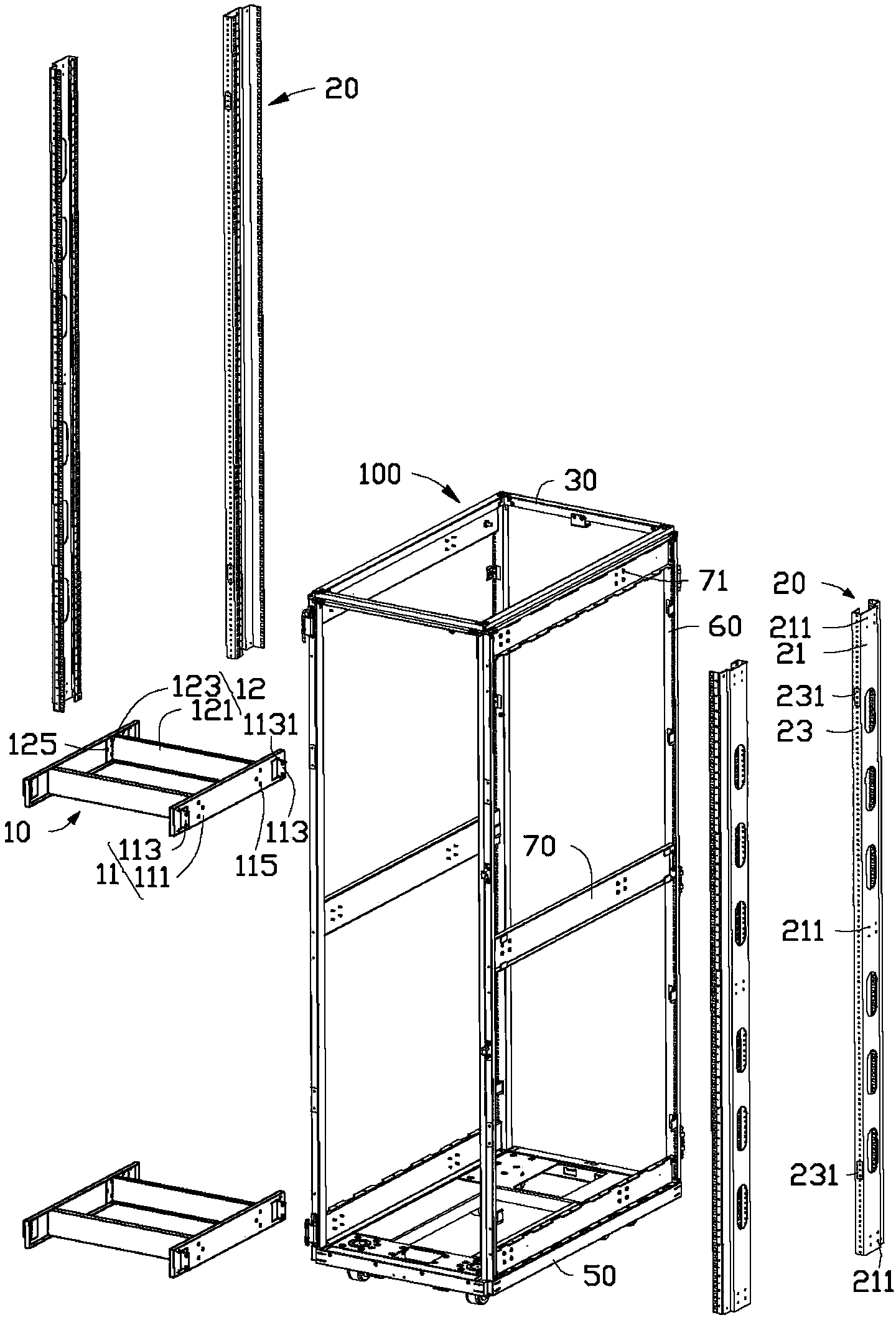
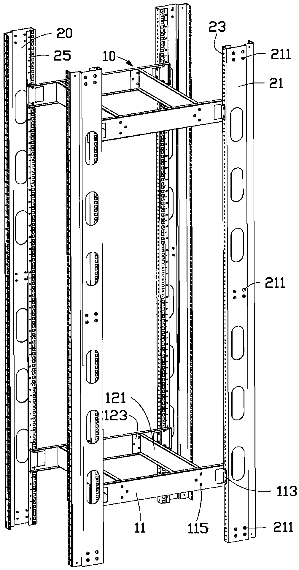
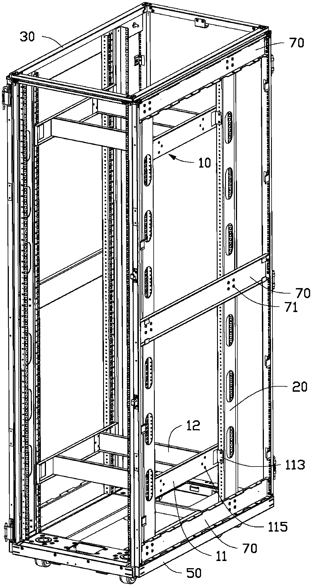
[0020] Please refer to figure 1 In a preferred embodiment of the present invention, two installation fixtures 10 are used to install four uprights 20 in a cabinet 100.

[0021] Each installation jig 10 includes two first positioning plates 11 and two second positioning plates 12. Each first positioning plate 11 includes a first plate 111 and a mounting piece 113 extending vertically outward from the outer surface of the first plate 111. The first plate 111 defines two sets of first fixing holes 115. There are three first fixing holes 115 in each group, and they are connected to form a triangle. Each mounting piece 113 defines two first mounting holes 1131. Each second positioning plate 12 includes a second plate 121 and two locking pieces 123 that are bent perpendicularly from two ends of the second plate 121 respectively. Each locking piece 123 defines three second fixing holes 125 corresponding to a group of first fixing holes 115. The two first plates 111 are parallel to e...


PUM


Abstract

A mounting fixture is used for installing several columns in a cabinet; the mounting fixture comprises two first positioning plates and two second positioning plates; each of the first positioning plates comprises a first plate body, and is used to be fixed to the column; each of the second positioning plates comprises a second plate body; the two second the positioning plates are fixed to the two first positioning plates; the two first plate bodies are parallel to each other; and the two second plate bodies are parallel to each other and perpendicular to the two first plate bodies.

Description

Technical field [0001] The invention relates to an installation jig, in particular to an installation jig used for installing a column in a cabinet. Background technique [0002] Four uprights are installed in the cabinet for fixing a number of electronic devices, such as uprights for servers. The four uprights surround and form a rectangular frame for stacking a number of servers. Usually, the four uprights are directly locked on the bearing plate of the cabinet by screws. However, in the process of screw locking, the relative positions of the four uprights can easily move, which will cause partial deformation of the rectangular frame surrounded by the four uprights, which makes the server squeezed or unable to be installed when the server is installed. Summary of the invention [0003] In view of the above, it is necessary to provide an installation jig that can prevent the column from moving during the installation process. [0004] An installation jig for installing a number ...

Claims


Application Information

Patent Timeline
Patent Type & Authority Applications(China)
IPC IPC(8): H05K7/14
Inventor 范振炉陈丽萍
Owner HONG FU JIN PRECISION IND (SHENZHEN) CO LTD
Why Eureka
Try Eureka