Electric objective table

A stage, electric technology, applied in the direction of the machine/support, supporting machine, mechanical equipment, etc., can solve the problem of difficult and precise positioning of the stage, and achieve the effect of not easy to move and high stability

Inactive Publication Date: 2013-07-17
KUN SHAN POWER STENCIL
View PDF10 Cites 15 Cited by
  • Summary
  • Abstract
  • Description
  • Claims
  • Application Information

AI Technical Summary

Problems solved by technology

[0010] The technical problem to be solved by the present invention is that the object stage in the prior art is not easy to be posi

Method used


Image

  • Electric objective table
  • Electric objective table
  • Electric objective table

Examples


Example Embodiment

[0035] [Example 1]

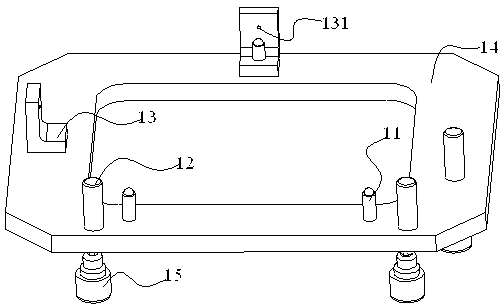
[0036] A stage with electric control position, such as figure 1 As shown, it includes a support column 11, a pin 12, a plunger 13, a fixed base plate 14, and a motor 15 that can rotate the pin 12 and the support column 11. In this embodiment, there are three supporting pillars 11 and they are not on the same plane. Since the three points are fully positioned and satisfy the geometric three-point fixed plane, the three upper ends of the supporting pillars can determine the loaded object on a plane.

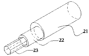
[0037] Pin 12 is an eccentric pin, such as figure 2 As shown, it consists of a part contacting the carried object 21, a part 22 fixed on the substrate 14 and a mechanism 23 part whose lower end is matched with the electrode. The position of the carried object placed on the support column can be adjusted by the rotation of the pin.

[0038] The part of the support column 11 fixed on the base plate 14 and the lower end have a mechanism part matched with the motor. The ...

Example Embodiment

[0045] [Example 2]

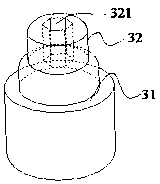
[0046] An electronically controlled position stage, which includes the stage and three eccentric pins that control the position of the loaded object. The eccentric pins have an adjustment function and can accurately determine the loaded object on a certain plane. The role of location. The eccentric pin with adjustment function is an eccentric pin, which is composed of two cylinders with different shafts. The surfaces of the two cylinders have a threaded structure. The eccentric pin is fixed on the stage through this structure for preventing loosening The nut fixes the adjusted eccentric pin on the stage, and there is an adjustment mechanism on the eccentric pin. In this embodiment, the adjustment mechanism is a circular hole, which can be rotated and adjusted by inserting a bar into it.

[0047] The stage in this embodiment has three hard-point support columns, which can fix the loaded object on a certain plane through the three support points, and the height ...

Example Embodiment

[0051] [Example 3]

[0052] An electrically controlled position-controlled object table is used to place objects with regular appearance and high position accuracy requirements. The support frame includes a support column, an eccentric pin, and a base for fixing the support column and the eccentric pin. The support columns are three hard support columns whose positions are not in a straight line, which are made of stainless steel and have a threaded structure that can rotate the support column at the contact position of the support column and the base, that is, it can be adjusted by the threaded structure The height of the support point of each support column. Three supporting columns can fix the supported table on a certain plane. In this embodiment, three eccentric pins are fixed on the base, which are made of hard wear-resistant materials. The position of the eccentric pins is on the periphery of the triangle formed by the support column and is not on a straight line. The fix...


PUM


Abstract

The invention relates to an electric objective table, which mainly solves the problem that the objective table can not be precisely positioned in the prior art. The objective table capable of electrically controlling the position comprises a base station, shores, plunger pistons, eccentric pins and a motor, wherein the shores, the plunger pistons and the eccentric pins are fixedly arranged on the base station; in the direction vertical to the base station, the height of the eccentric pins and the plunger pistons is more than the height of the shores; a plane is formed by the vertexes of the supporting positions of the shores; a carried objective is arranged on the supporting positions of the shores; the edge of the carried objective is contacted with the eccentric pins and the plunger pistons; at least one plunger piston is positioned on the relative position of the eccentric pin; and the lower ends of the eccentric pins and the shores are provided with a rotation mechanism cooperated with the motor. According to the technical scheme that the motor position is fixed below the eccentric pins and the shores, the problem is better solved, and the electric objective table can be used for the industrial production of the objective table for the precise operation.

Description

[0001] technical field [0002] The invention relates to an electric stage. Background technique [0003] With the development of society, various industries have higher and higher requirements for the placement environment and bearing platform of the hardware facilities involved in the industry, especially for the placement of some precision instruments. For example, in the operation table involving the work of optical components, it is often required that the supporting platform has sufficient stability. [0004] Chinese patent CN101738127A discloses a heat-insulating support device, which includes a cold platform with multiple mounting holes and a support rod for supporting the cold platform, and the support rod includes an upper support rod and a lower support rod. Cooperate with the mounting holes in a point contact or line contact manner respectively, but the support frame of the invention has four support columns. [0005] Chinese patent CN2574502 discloses a three-...

Claims


Application Information

Patent Timeline
IPC IPC(8): F16M11/04F16M11/18F16M11/32
Inventor 魏志凌高小平
Owner KUN SHAN POWER STENCIL
Why Eureka
Try Eureka